Basic Definitions
I created this page for my notes on various topics of EE. I will be discussing basic topics and how to derive them.
These are the four newest kits I purchased:
161 pcs 20 models, Each with individual compartment. Pin assignment table included.
IC Plier included for easy picking and removing IC
Op Amp: LM358 LM324 JRC4558 NE5532 LM386 TDA2030 TDA2822 UA741 Comparators: LM393 LM339
PhotoCoupler: PC817 Multivibrator: CD4047 Analog Multiplexer: CD4053 Echo Audio Processor: PT2399
PWM controller: UC3842 UC3843 Darlington Array ULN2003 ULN2803, Voltage Converter 7660 Timer: NE555
Useful 40 Values Resistors: 1Ω,2.2Ω,3.3Ω,4.7Ω,10Ω,22Ω,47Ω,68Ω,100Ω,120Ω,150Ω,220Ω,270Ω,330Ω,470Ω,560Ω,680Ω,750Ω,820Ω,910Ω,1KΩ,2KΩ,2.2KΩ,4.7KΩ,5.6KΩ,7.5KΩ,10KΩ,22KΩ,47KΩ,68KΩ,100KΩ,150KΩ,220KΩ,470KΩ,560KΩ,680KΩ,750KΩ,820KΩ,910KΩ,1MΩ
10pf – 10uf 30 value 300 pcs capacitor set, 30 individual compartment
Each compartment has a plastic cover/door that opens and closes with a nice positive snap.
10pf 15pf 22pf 33pf 47pf 68pf 100pf 220pf 470pf 680pf
inf 2.5nf 2.2nf 3.3nf 4.7nf 6.8nf 10nf 22nf 47nf 68nf
0.1uf 0.15uf 0.22uf 0.33uf 0.47uf 0.68uf 1uf 2.2uf 4.7uf 10uf
0.1uF – 2200uf 20 value 304 pcs capacitor set
See through the bottom of the transparent trays
0.1, 0.22, 0.47, 1, 2.2, 3.3, 4.7, 10, 22, 33, 47, 100, 220, 470, 1000, 2200uf capacitance
10V, 16V, 25V, 50V voltage limit
Each compartment has a plastic cover/door that opens and closes with a nice positive snap
Ampere: is a unit of measure of the rate of electron flow or current in an electrical conductor. One ampere of current represents one coulomb of electrical charge (6.24 x 10 18 charge carriers) moving past a specific point in one second.
Capacitor: a device used to store an electric charge, consisting of one or more pairs of conductors separated by an insulator.
Capacitance: the ability of a system to store an electric charge. The ratio of the change in an electric charge in a system to the corresponding change in its electric potential.
Circuit: a complete and closed path around which a circulating electric current can flow.
Coulomb: the SI unit of electric charge, equal to the quantity of electricity conveyed in one second by a current of one ampere. The coulomb (symbol: C) is the International System of Units (SI) unit of electric charge. Under the 2019 redefinition of the SI base units, which took effect on 20 May 2019, the coulomb is exactly 1/(1.602176634×10 ) elementary charges. The same number of electrons has the same magnitude but opposite sign of charge, that is, a charge of −1 C.
Current: is the rate at which electrons flow past a point in a complete electrical circuit. At its most basic, current = flow. An ampere (AM-pir), or amp, is the international unit used for measuring current.
Diode: is a two- terminal electronic component that conducts current primarily in one direction (asymmetric conductance ); it has low (ideally zero) resistance in one direction, and high (ideally infinite) resistance in the other. A diode vacuum tube or thermionic diode is a vacuum tube with two electrodes,…
Electric potential energy: is a potential energy (measured in joules) that results from conservative Coulomb forces and is associated with the configuration of a particular set of point charges within a defined system. An object may have electric potential energy by virtue of two key elements: its own electric charge and its relative position to other electrically charged objects.
Farad: the SI unit of electrical capacitance, equal to the capacitance of a capacitor in which one coulomb of charge causes a potential difference of one volt.
Ground: in the context of electronics, is the reference point for all signals or a common path in an electrical circuit where all of the voltages can be measured from. This is also called the common drain since the voltage measurement along it is zero.
Henry: The henry (symbol: H) is the SI derived unit of electrical inductance. If a current of 1 ampere flowing through a coil produces flux linkage of 1 weber turn, that coil has a self inductance of 1 henry. The unit is named after Joseph Henry (1797–1878), the American scientist who discovered electromagnetic induction independently of and at about the same time as Michael Faraday (1791–1867) in England.
Indcutance: the property of an electric conductor or circuit that causes an electromotive force to be generated by a change in the current flowing.
Inductor: also called a coil, choke, or reactor, is a passive two-terminal electrical component that stores energy in a magnetic field when electric current flows through it.[1] An inductor typically consists of an insulated wire wound into a coil.
When the current flowing through the coil changes, the time-varying magnetic field induces an electromotive force (e.m.f.) (voltage) in the conductor, described by Faraday‘s law of induction. According to Lenz’s law, the induced voltage has a polarity (direction) which opposes the change in current that created it. As a result, inductors oppose any changes in current through them.
An inductor is characterized by its inductance, which is the ratio of the voltage to the rate of change of current. In the International System of Units (SI), the unit of inductance is the henry (H) named for 19th century American scientist Joseph Henry. In the measurement of magnetic circuits, it is equivalent to weber/ampere. Inductors have values that typically range from 1 µH (10−6 H) to 20 H. Many inductors have a magnetic core made of iron or ferrite inside the coil, which serves to increase the magnetic field and thus the inductance. Along with capacitors and resistors, inductors are one of the three passive linear circuit elements that make up electronic circuits. Inductors are widely used in alternating current (AC) electronic equipment, particularly in radio equipment. They are used to block AC while allowing DC to pass; inductors designed for this purpose are called chokes. They are also used in electronic filters to separate signals of different frequencies, and in combination with capacitors to make tuned circuits, used to tune radio and TV receivers.
Ohm: the SI unit of electrical resistance, expressing the resistance in a circuit transmitting a current of one ampere when subjected to a potential difference of one volt.
Resistance: the degree to which a substance or device opposes the passage of an electric current, causing energy dissipation. Ohm’s law resistance (measured in ohms) is equal to the voltage divided by the current. A resistor of 1Ω will allow a current of 1A when the potential difference between the ends of the resistor is 1V.
Resistor: is a passive two-terminal electrical component that implements electrical resistance as a circuit element. In electronic circuits, resistors are used to reduce current flow, adjust signal levels, to divide voltages, bias active elements, and terminate transmission lines, among other uses. High-power resistors that can dissipate many watts of electrical power as heat, may be used as part of motor controls, in power distribution systems, or as test loads for generators. Fixed resistors have resistances that only change slightly with temperature, time or operating voltage. Variable resistors can be used to adjust circuit elements (such as a volume control or a lamp dimmer), or as sensing devices for heat, light, humidity, force, or chemical activity.
Volt: the SI unit of electromotive force, the difference of potential that would drive one ampere of current against one ohm resistance.
Voltage: an electromotive force or potential difference expressed in volts. It is the pressure from an electrical circuit’s power source that pushes charged electrons (current) through a conducting loop, enabling them to do work such as illuminating a light. In brief, voltage = pressure, and it is measured in volts (V).
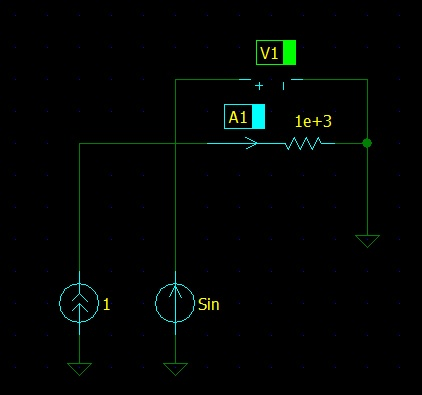
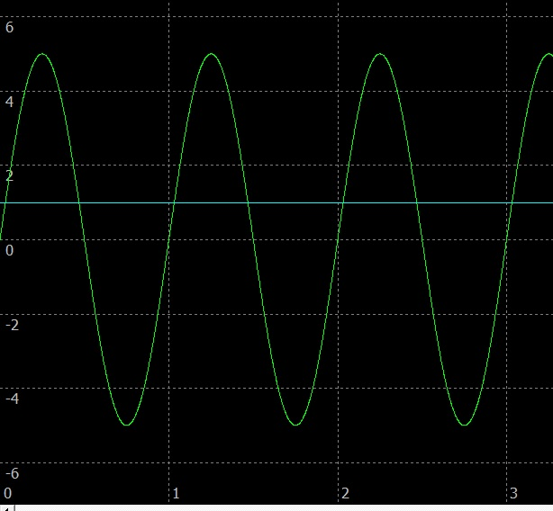
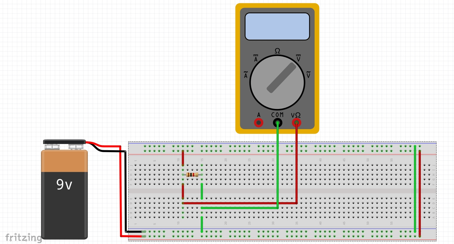
Using a multimeter to measure voltage and current. You never put a meter across a battery without a load to measure current. You will blow up your meter. You never measure current in parallel with the load either. Same results, BOOM!. You need to measure current in series with the load. On the right side you see the schematic layout with A1 (current probe) and V1 (voltage probe). The scope view below it shows the sine wave with 5V and period of 1 second. The straight line is the current of 1A.
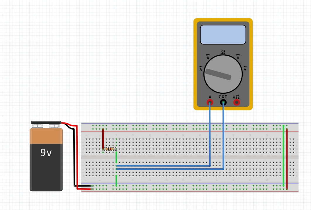
Since the internal resistance of a multimeter is high you can measure the voltage directly from a battery without a load present. Make sure you have your multimeter set to DC Voltage. You can remove the resistor and measure directly from the battery with the meter in DC Voltage mode.
Ohm’s Law:
V = I * R
Power(Watts) = V * I or I * I * R = I2 * R
Power(Watts) = V2 / R