import RPi.GPIO as GPIO
import time
from smbus import SMBus
ard_addr = bytearray([0x04, 0x05, 0x06, 0x07, 0x09, 0x0a, 0x0b, 0x0c])
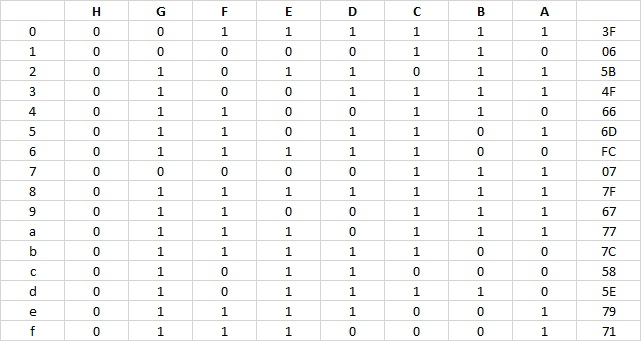
led_addr_MSB = bytearray([0x66, 0x6d, 0xfc, 0x07, 0x67, 0x77, 0x7c, 0x58])
bus = SMBus(1) # indicates /dev/ic2-1
LSBFIRST = 1
MSBFIRST = 2
dataPin = 11 #DS Pin of 74HC595(Pin14)
latchPin = 13 #ST_CP Pin of 74HC595(Pin12)
clockPin = 15 #CH_CP Pin of 74HC595(Pin11)
def setup():
GPIO.setwarnings(False)
GPIO.setmode(GPIO.BOARD)
GPIO.setup(dataPin, GPIO.OUT)
GPIO.setup(latchPin, GPIO.OUT)
GPIO.setup(clockPin, GPIO.OUT)
def shiftOut(dPin,cPin,order,val):
for i in range(0,8):
GPIO.output(cPin,GPIO.LOW);
if(order == LSBFIRST):
GPIO.output(dPin,(0x01&(val>>i)==0x01) and GPIO.HIGH or GPIO.LOW)
elif(order == MSBFIRST):
GPIO.output(dPin,(0x80&(val<<i)==0x80) and GPIO.HIGH or GPIO.LOW)
GPIO.output(cPin,GPIO.HIGH);
def loop():
cnt = 0
while True:
cnt = 0
GPIO.output(latchPin,GPIO.LOW)
shiftOut(dataPin,clockPin,LSBFIRST,0x00)
GPIO.output(latchPin,GPIO.HIGH)
time.sleep(0.1)
while cnt < 8:
# turn on LED 13
bus.write_byte(ard_addr[cnt], 0x1) #switch it on
GPIO.output(latchPin,GPIO.LOW)
shiftOut(dataPin,clockPin,MSBFIRST,led_addr_MSB[cnt])
GPIO.output(latchPin,GPIO.HIGH)
time.sleep(2)
# turn off LED 13
bus.write_byte(ard_addr[cnt], 0x0) #switch it off
time.sleep(2)
# blank
GPIO.output(latchPin,GPIO.LOW)
shiftOut(dataPin,clockPin,LSBFIRST,0x00)
GPIO.output(latchPin,GPIO.HIGH)
time.sleep(0.1)
cnt += 1
def destroy():
GPIO.cleanup()
if __name__ == '__main__':
print ('Program is starting...' )
setup()
try:
loop()
except KeyboardInterrupt:
destroy()
I combined the 7 Segment display of the Raspberry Pi and the 8 Arduino LED 13 code. I tightened up the code. This one uses the MSB logic table below.