Husband to an amazing wife and two adorable children. This website covers electrical engineering projects. I have Arduinos and a Raspberry Pi. The EE Lab has everything that I had available at university. This lab has grown and changed over 20+ years. You will learn C# (Arduino) and Python (Raspberry Pi). It covers circuit design. I have 30+ sensors that can be integrated.
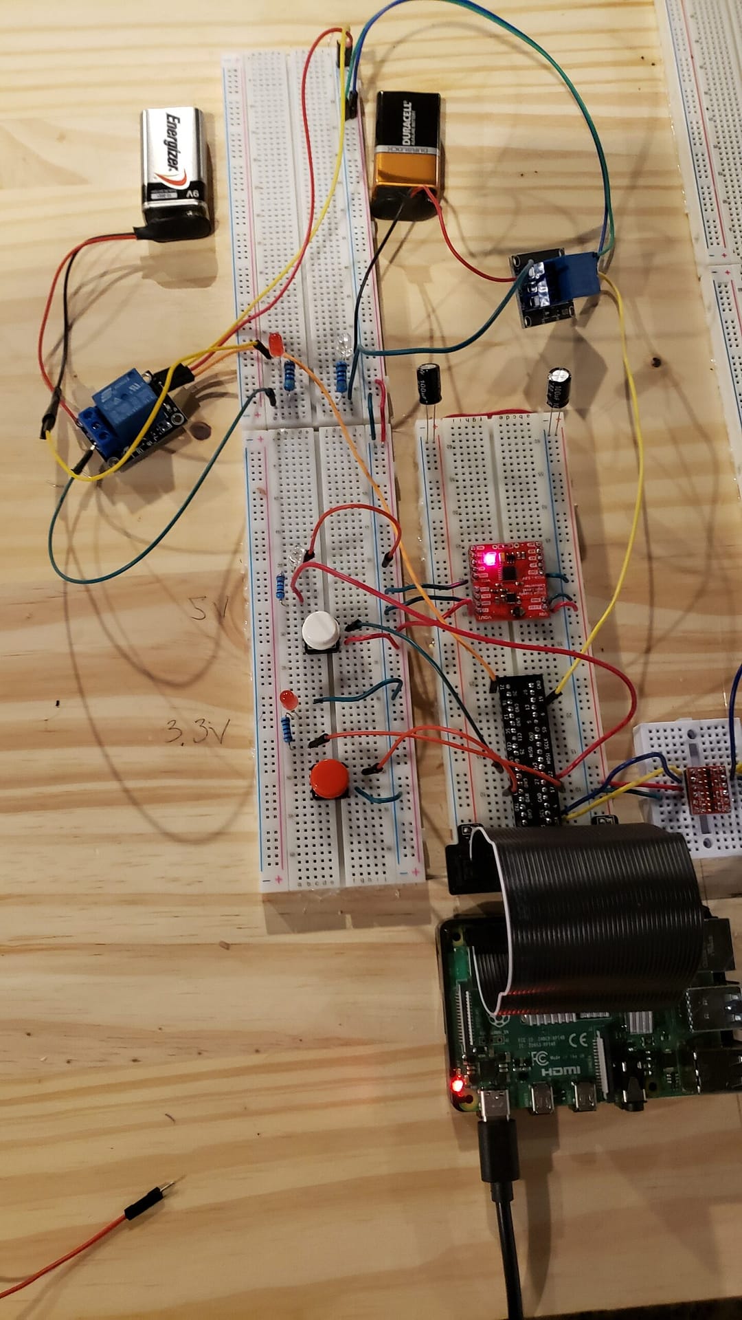
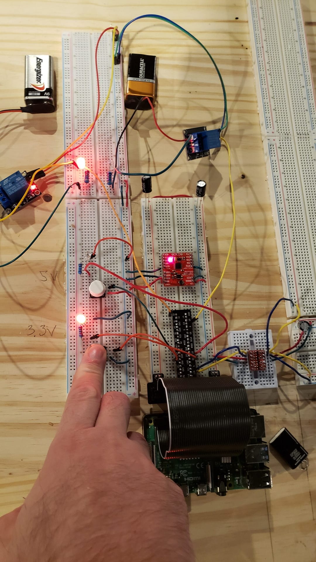
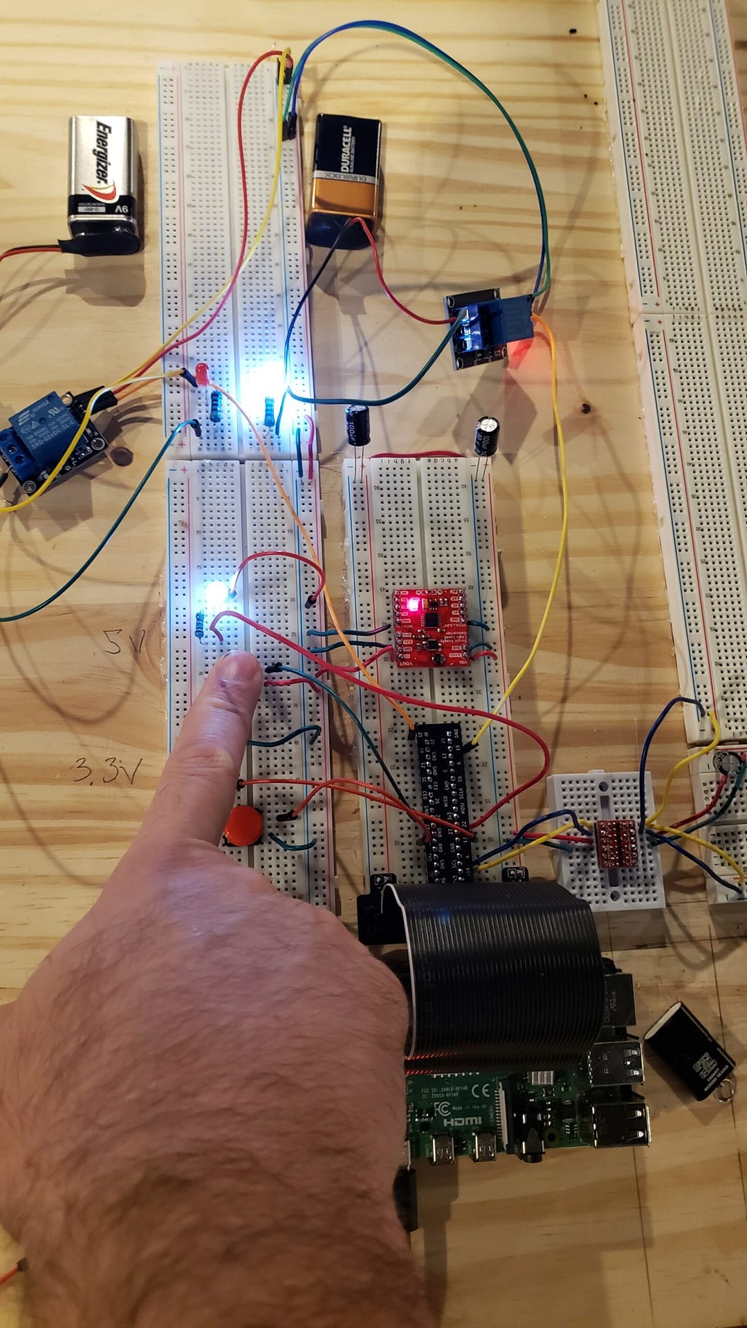
pi_relay
I am using the Single Supply Level Logic Converter to get 5V for this project.
We will start with the 9V battery side of the relay. Yes, I could use 120V or higher devices. 9V is safe for novices.
9V battery – 1.5V Red LED = 7.5V needs to be dissipated to save the Red LED. Red LED is known to be 1.5V @ 20mA. So 7.5V / 0.020A = 375 Ω for the minimum resistance. You have seen this on other projects of mine that I use a 470 Ω resistor for a Red LED on a 9V battery. Red button is for Red LEDs. White button is for White LEDs. pd = Pull Down and pu = Pull Up. Full code at bottom.