Husband to an amazing wife and two adorable children. This website covers electrical engineering projects. I have Arduinos and a Raspberry Pi. The EE Lab has everything that I had available at university. This lab has grown and changed over 20+ years. You will learn C# (Arduino) and Python (Raspberry Pi). It covers circuit design. I have 30+ sensors that can be integrated.
Homepage
mc for microcontroller
I have both Arduino and Raspberry Pi devices. I might expand into other microcontroller units. I am redesigning this web site to be more mobile friendly. It will take time to get all 90+ pages done.
I have my Bachelor of Electrical Engineering degree from University of Detroit Mercy class of 1996. I went into cyber security and network engineering. A few years ago on Facebook I saw an ad for an Arduino Starter Kit. I had a lot of fun with it so I added to my collection. I have 9 Arduino devices and a Raspberry Pi 4B 8GB.
My goal of this page is to educate and mentor you in STEM. I will teach you Science, Technology, Engineering and Mathematics or STEM. I am starting with the definitions and information about each components. As I move more of my projects into each area, I will expand on why you use certain components and how to use them. Design choices will come into play. I am going to organize everything better in the menus.
My page is free and not monetized. I still don’t mind posting where I get my components from. These are smaller companies that deserve our support. You can tell Sparkfun components because they are red. I have been working with Austin and Alex at Invenr.io to expand their product line and help with with new projects.
Where to start with your Raspberry PI microcomputer and the Arduino microcontroller?
Go to my I2C section above. I purchased a chip from Sparkfun to connect the 3.3V Rasapberry Pi 4B 8GB as the master to my 5V Arduinos (9 of them). The Raspberry Pi allows you to install a Linux OS on the SD card. MY Raspberry Pi 4B 8GB is a quad core 64-bit processor.
I am amazed about the selection of both Arduino devices and Raspberry Pi devices available in the market place.
I heard Raspberry Pi vs. Arduino being compared like Coke vs. Pepsi. Some say you can do more with a Raspberry Pi than an Arduino. As an engineer, I say, they are tools that have a purpose.
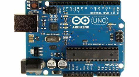
Arduino Uno
Comes in many types with different pin outs. You can get a them to build wearables to Mega Wifi. You can add shields on top to expand them. The nice thing is open the IDE and write the code and it runs. No fuss. You can connect them up with USB cables to program them. I purchased a 9V 1A power supply for mine. They come with a 9V battery cable.
They come with Analog and Digital GPIO pins. You can use them with 3.3V and 5V components. You can expand them with I2C, SPI and UART buses. I will be using the I2C bus because of all the cool components you can get for them. 4 pins: VCC, Ground, Data (SDA) and Clock (SCL). That is it. You address each component by soldering pins or jumpers. I love I2C because I hate wires. I started using shift registers.
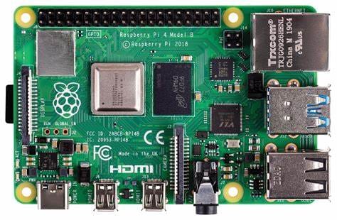
Raspberry Pi 4B
I don’t like that the pins are not labelled. I bought it to build my 5 year old daughter a Minecraft server. After three attempts. I pulled out my Xbox 360 and put it on that. I wanted it to play on her tablet on a server I controlled. I put the Raspberry Pi to better use. I added it to my Arduino I2C bus. May 2021, Raspbian released a 64-bit version of their OS for the Raspberry Pi. It included the 5.11 kernel. Arduino devices were ready to serve as I2C slaves. I bought the Canakit version with case, fan, etc. It is cool, you have a HDMI on it. I read I can build a NAS with it. I saw someone put a weather station on it with a battery pack. They put them in weather proof cases in the ocean. It comes in many types with different pin outs. You can get a them to build wearables to Ethernet/Wifi. My first Raspberry Pi was the 64-bit 8GB Raspberry Pi 4B. I put a type 10 256GB SD card that was recommended in it. Check out my Raspberry Pi pages.
Pi has only 3.3V and digital pins on it. You can use a A-D converter and I can use the PWM pins to simulate analog.
It can do I2C but only at 3.3V. So you need a bi-directional logic level converter I2C bus. On one side Pi country 3.3V, ground, SDA, and SCL. On the other side Arduino country with 5V, Ground, SDA, and SCL
Finally, it came in stock at Inventr.io.
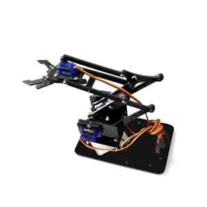
The classic 4 degree-of-freedom robotic arm is inspired by industrial robots commonly used in factories around the world. The kit is great for any maker space, college students, high school students, or learning centers. You can use Arduino, HERO, 51 single chip, model remote control, etc. to control the robotic arm.
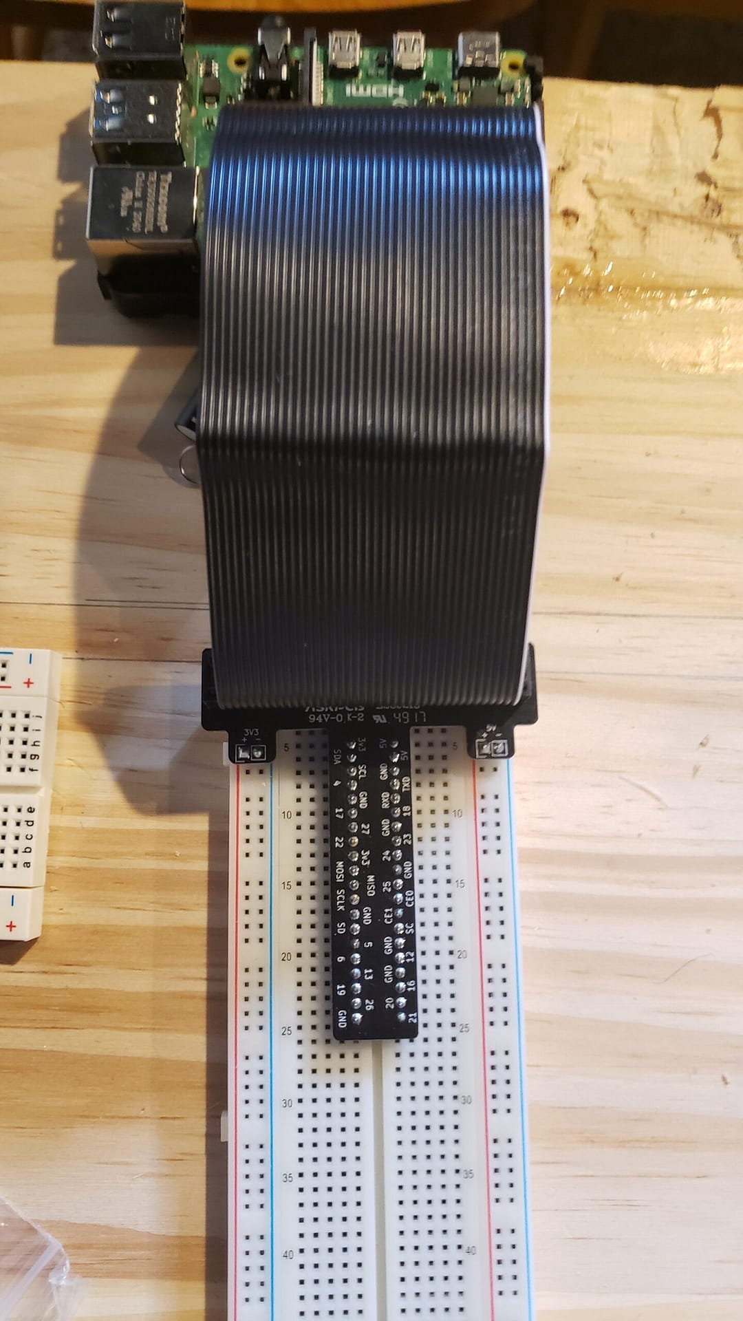
This is the Raspberry Pi T-Cobbler Pro. This one I bought at Micro Center. My only issue with the Raspberry Pi is none of the pins are labelled. This device helps with labelng the pins but gives you a handy 3.3V and 5V power rail. Left side you see 3.3V power and ground and the right side 5V power and ground. Most recommend not to use the 5V rail because it is not a true 5V rail like the Arduino. I am still trying to find a Fritzling version of my T-Cobbler Pro component.
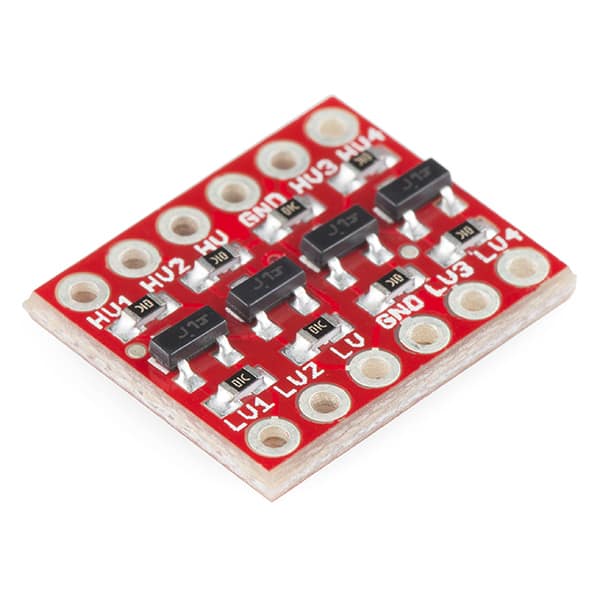
Bi-Directional Logic Level Converter for I2C. This is an inexpensive solution to connect a Raspberry Pi on 3.3V to Arduino devices on 5V and move data between them. Raspberry Pi is the master device. I connected the I2C LCD screens to the Raspberry Pi and displayed the data from the Arduino devices to them. I2C section in the menu shows pictures of the connection. I am staying with yellow and blue I2C wiring for the bus configuration.
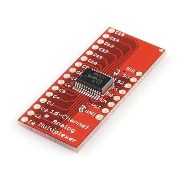
16 Channel Analog to Digital Converter is a great component to add to your collection. An Arduino Nano has one Analog channel on it. This gives you the functionality of adding 16 analog devices. The loop feature is so fast you can go through all 16 channels in almost real time for photo resistors, temperature and humidity and other analog components.
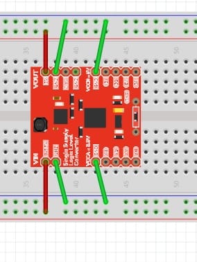
Single Supply Logic Level Converter is a handy component to add to your projects.
Single Source Logic Level Converter. It is not capable of i2C but can be used to convert 5V components to be used on a Raspberry Pi or Arduino Nano. It is capable to taking a 3.3V VCC In and converting it to 5V VCC Out. The right side shows the wiring diagram in a simgle form. The wiring of the SSLLC is VCC and ground on the left side of the component provides 3.3V on lower side and 5V on the higher side. The right side of the component has the common ground and 4 pass through pin sets. You need the common ground for components to function properly.