Husband to an amazing wife and two adorable children. This website covers electrical engineering projects. I have Arduinos and a Raspberry Pi. The EE Lab has everything that I had available at university. This lab has grown and changed over 20+ years. You will learn C# (Arduino) and Python (Raspberry Pi). It covers circuit design. I have 30+ sensors that can be integrated.
Arduino
I tore down my old setup. The 2 x 4 board with all the Arduinos and Raspberry Pi is no longer. The Lost in Space Project will be upgraded. Organizing everything into storage allowed me to find breadboard power supply modules. No longer will the bread boards use Arduino power.
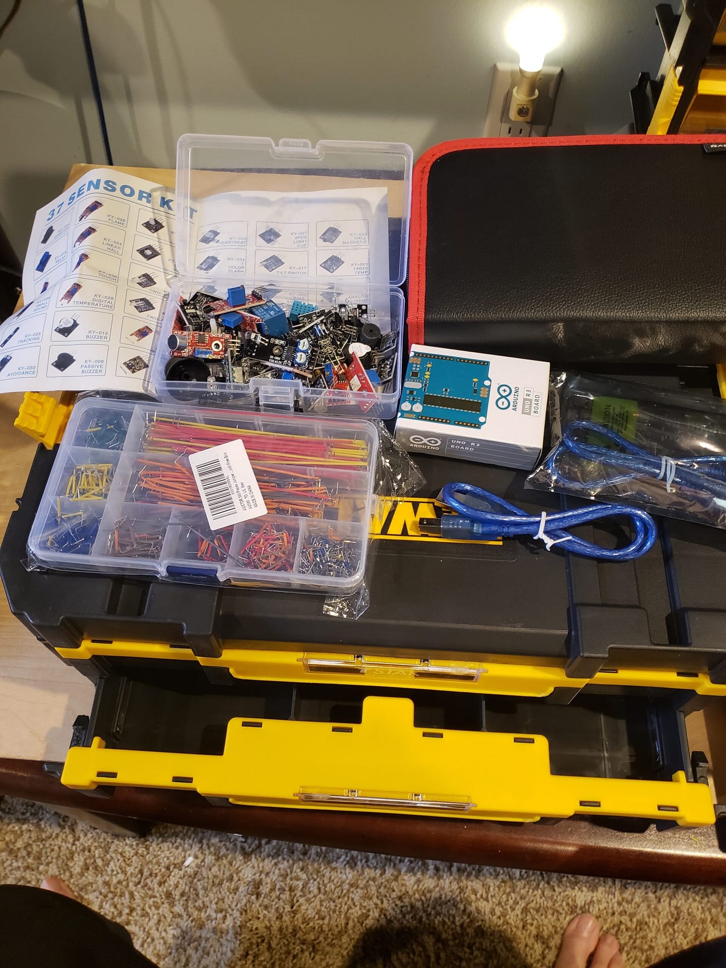
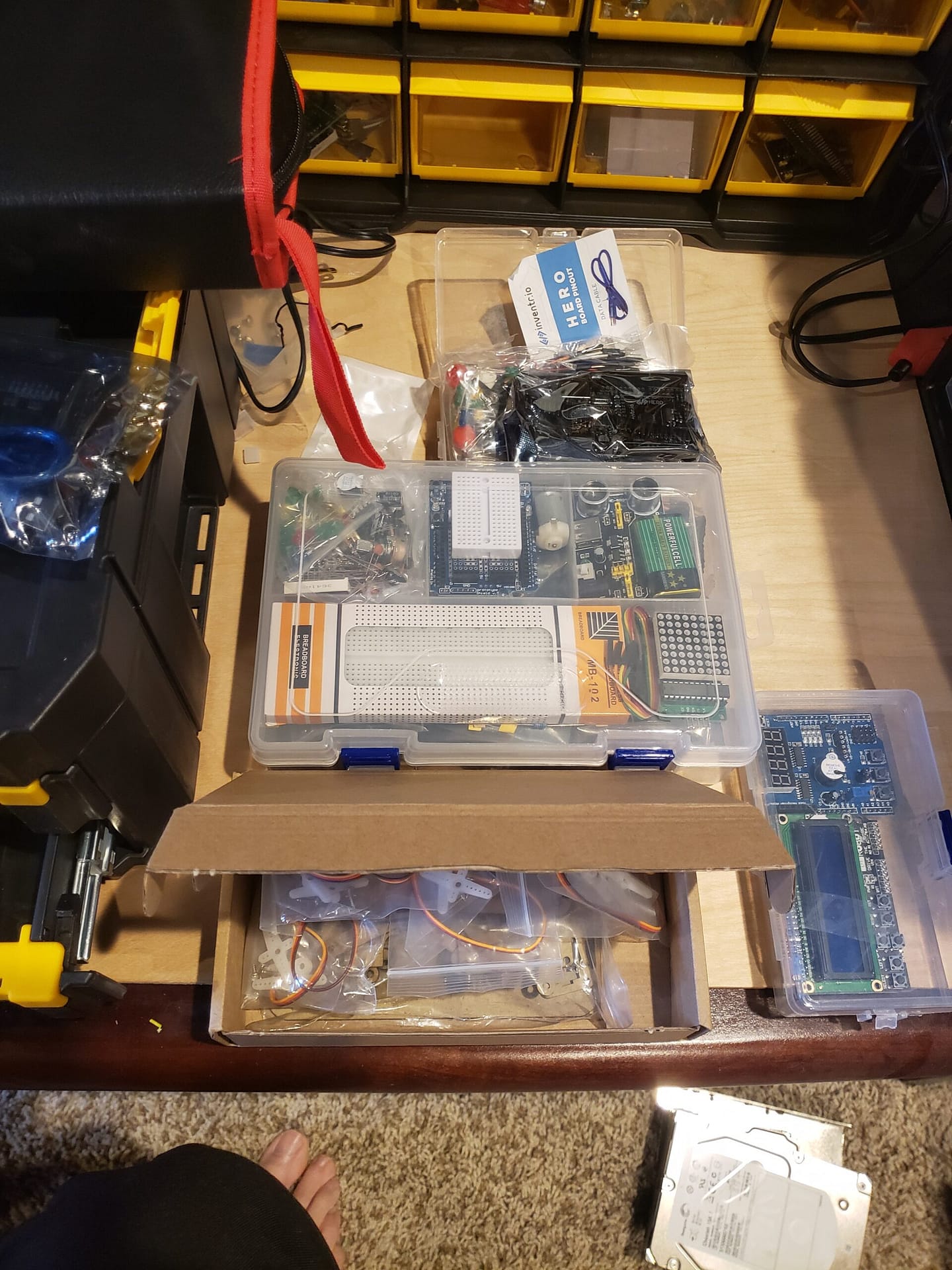
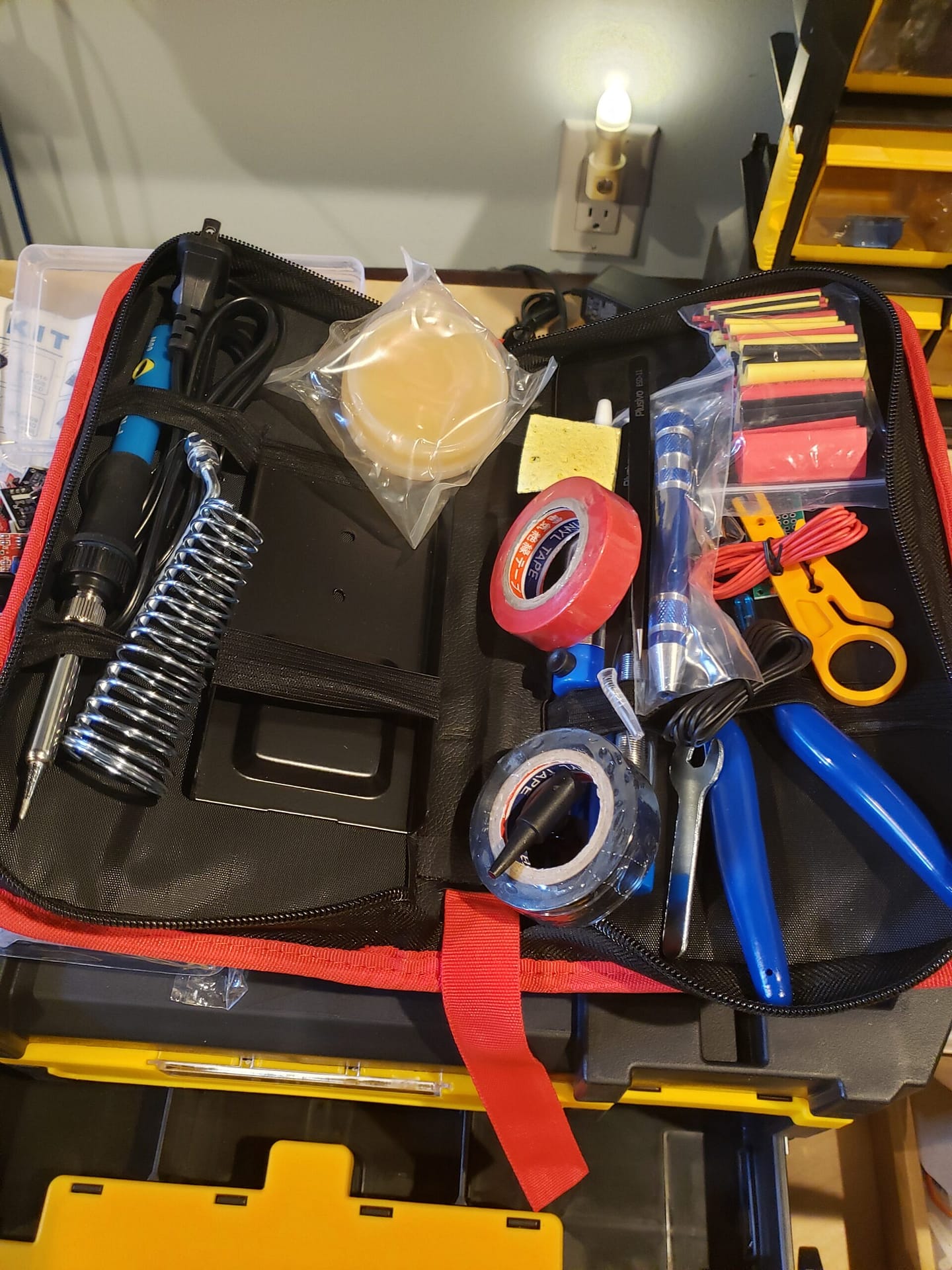
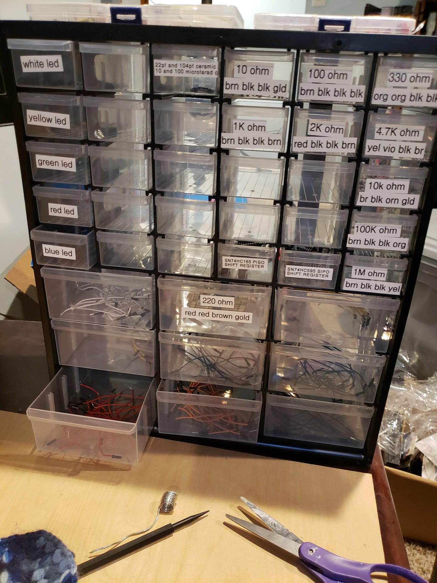
My EE Lab is growing, A trip to Lowes came back with various Craftsman Small Parts Cabinets. It allowed me to organize my resistors, capacitors, shift registers, op-amps, sensors, Raspberry Pi, Arduino, wires, and other components. I will be adding new pictures of my EE Lab. I have a Siglent oscilloscope, digital multimeter, soldering station, glue gun, and bunch of bread boards.
To power my devices, I picked up 9V-1A power supplies, toggle switches, and other bread boards to start building many amazing projects. Now I can connect my Raspberry Pi 4B 8GB device to connect to the Arduino I2C bus together with a SparkFun Logic Level Converter – Bi-Direction. You can see more on the Raspberry Pi pages.
/347 error on copying my arduino code
It is caused because ” in WordPress is unicode not Arduino code. You will need to replace every ” with new ones. I will see who I can get this resolved.
Christmas came early
Christmas came early. https://inventr.io/ send me a box of new components to produce interesting projects for them. Two more UNOs. A new project was combining a DC motor with a NPN transistor. In the future, I will do the same with a PNP transistor and show how the PWM works differently on them. More projects will have LCD displays.
EE Lab Organization
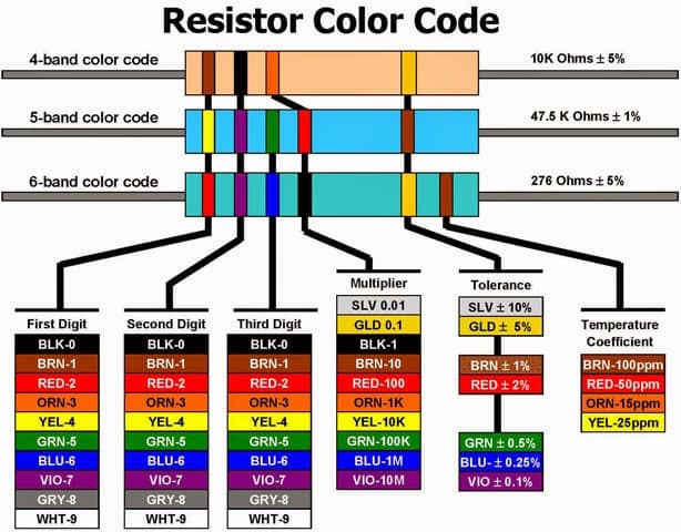
Understanding resistors
Working with these device to build projects is a lot of fun but you need to learn some basics of electronics. Below I provide you some of the charts and pictures to help you out. I created an entire section on Electrical Engineering to explain all the concepts, definitions and other information about V = IR. Circuit designs and other concepts that will expand what you can build with your Pi and Arduino devices.
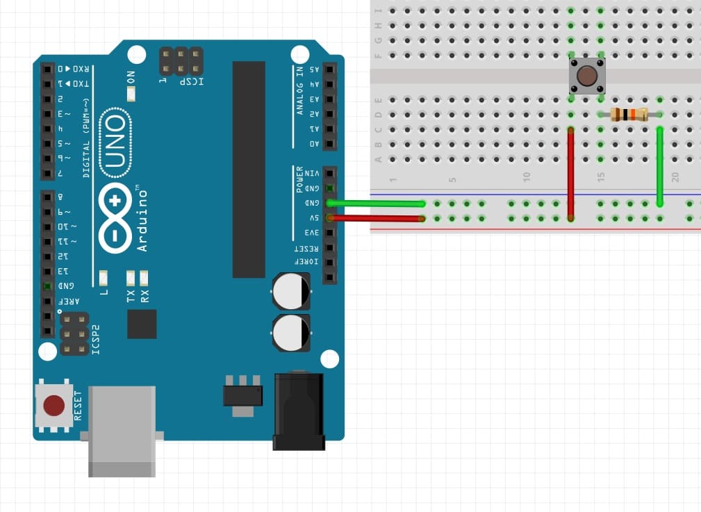
Pull Down Resistor: The 10kΩ resistor is connects the push button to the ground. Pulling down the voltage always to 0V
Button up: Open circuit. No current flows. No voltage drop across the 5V. The 10kΩ resistor is from the push button to the ground. If you did a digitalRead from the top of the resistor, read pin will see 0V or read a 0
Button down: Short/Closed: Current flows through the push button and leaves through the 10kΩ resistor to ground. If you did a digitalRead from the top of the resistor, read pin will see 5V or read a 1
Pull Up Resistors
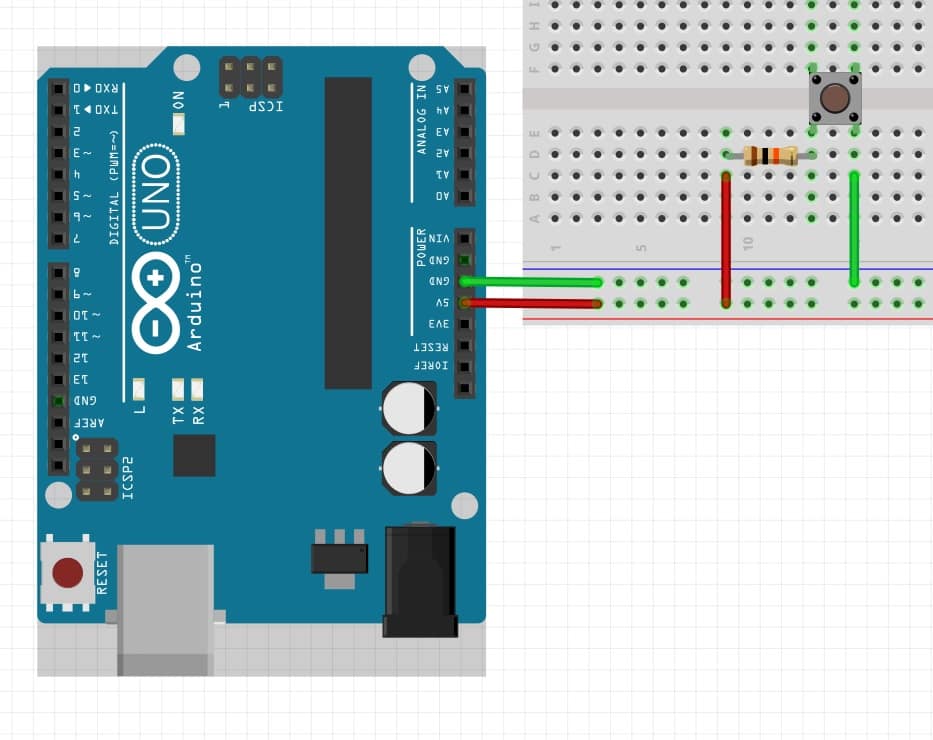
Pull up Resistor: The 10kΩ resistor is connects the push button to the VCC (5V). Pulling up the voltage always to 5V.
Button up: Open circuit. No current flows. No voltage drop across the 5V through 10kΩ resistor. If you did a digitalRead on other side of the resistor, read pin will see 5V and report a 1. You need to put a ground the resistor to measure it with a multi-meter.
Button down: short/current. Current flows through resistor and we get a voltage drop. If you have a digitalRead on other side of the resistor the read pin would read 0V and report a 0.
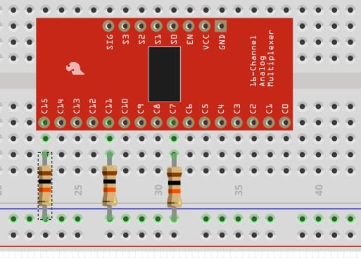
As you look at my projects for both the Raspberry Pi and Arduino device, you will see me use various pull-up and down-up resistors. I used pull -down resistors with my Sparkfun 16 channel Analog to Digital Converter to make sure empty channels, when sent to ground so the output voltage is 0 V. A pull up resistor is used on buttons limits the current going from VCC (3.3V or 5V) through the button and to ground so you do not damage your device. It prevents it from floating to an unknown value. Pull-down keeps it in a low state (0V to ground), or Pull-up keeps it in a high state to your VCC voltage.
The tolerance is +- 1%. The multimeter reads 1.003kΩ
Red – red – black – gold
Red: 2 Red: 2 Black: 0 Gold: +- 5%
220 ohms or 220Ω
The tolerance is +- 5%. The multimeter reads 214kΩ
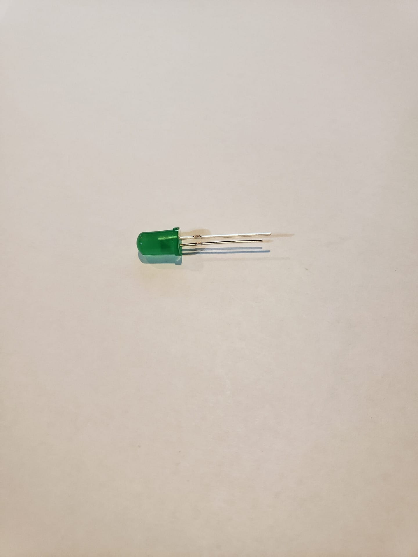
LEDs: Some basic knowledge.
The LED is 1.5V / 25mA, according to the site. You have a flat side that on the side of the shorter pin. This is the negative. The longer pin is the positive.
The device is 3.3V and 5V
My lab has many resistors from 1 Ω to 1 MΩ
5V: 5V – 1.5V = 3.5V has to be dissipated V = I x R or Voltage = current x resistance 3.5V = 0.025A x R R = 3.5V / 0.025A R = 140Ω
The smallest resistor you can use is 140Ω.
3.3V: 3.3V – 1.5V = 1.8V has to be dissipated V = I x R or Voltage = current x resistance 1.8V = 0.025A x R R = 1.8V / 0.025A R = 72Ω