Husband to an amazing wife and two adorable children. This website covers electrical engineering projects. I have Arduinos and a Raspberry Pi. The EE Lab has everything that I had available at university. This lab has grown and changed over 20+ years. You will learn C# (Arduino) and Python (Raspberry Pi). It covers circuit design. I have 30+ sensors that can be integrated.
Breadboard power supply
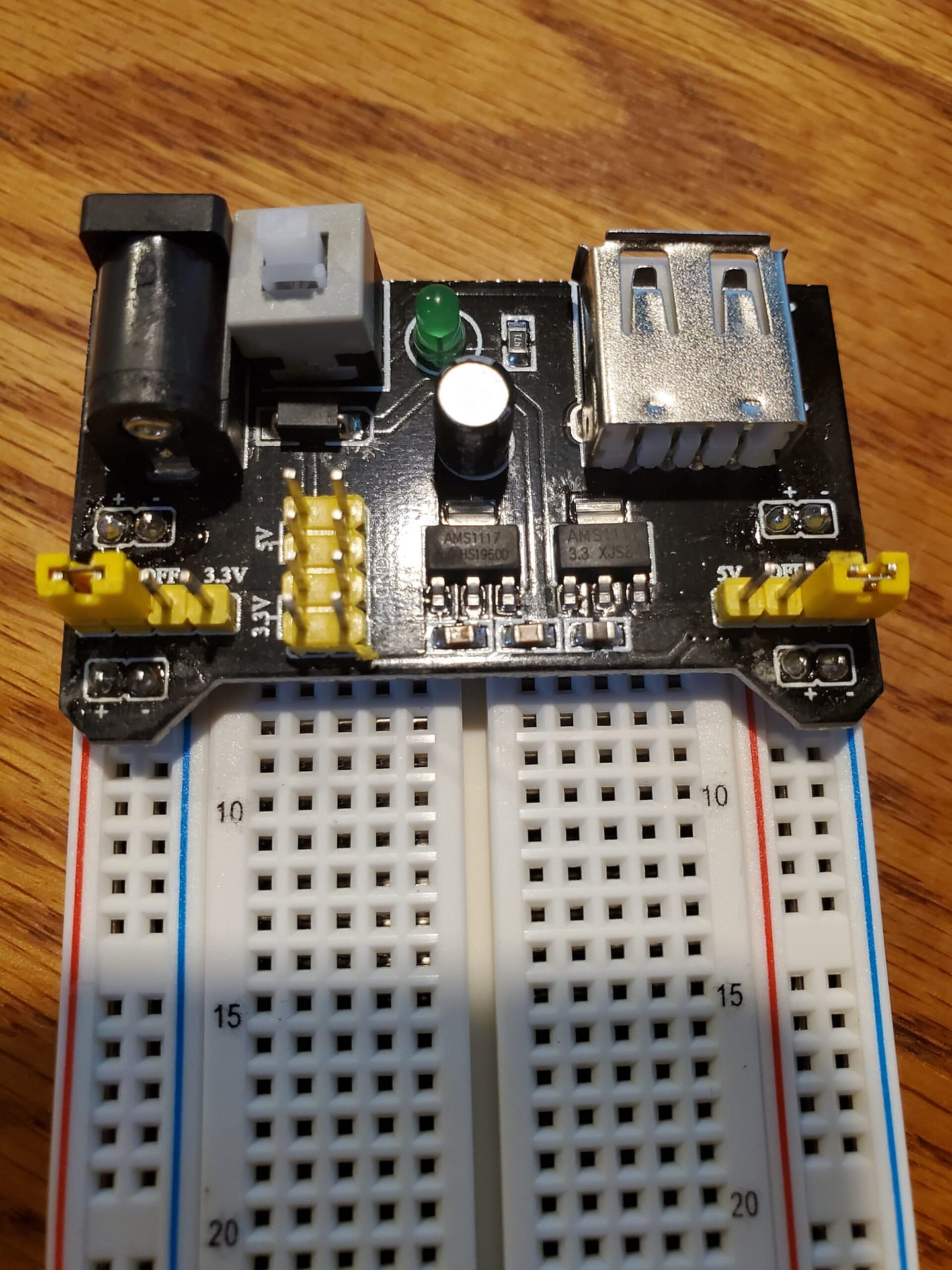
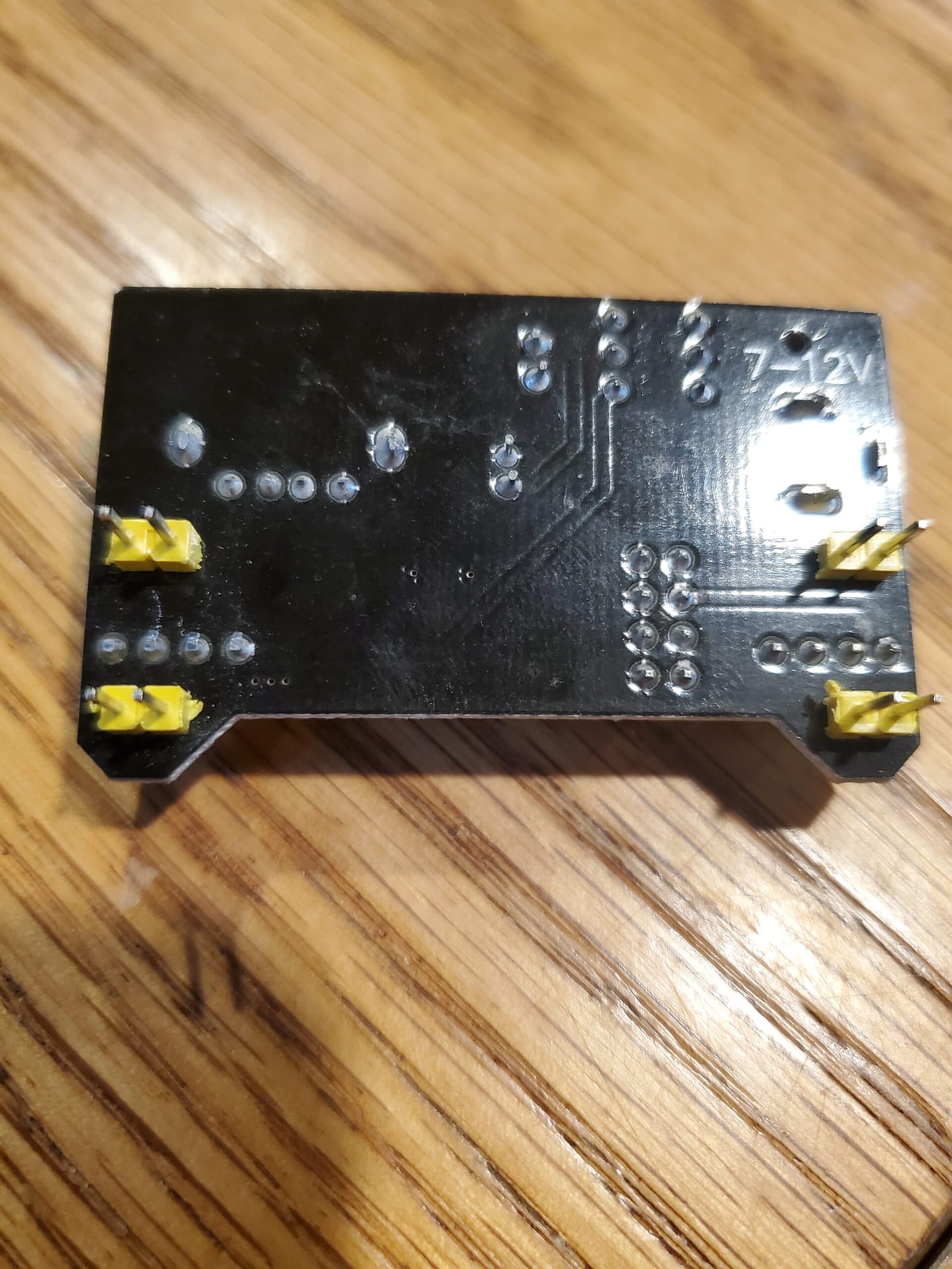
Instead of powering the breadboard from an Arduino or Raspberry Pi. I am using a breadboard power supply module. It is 7-12V capable. I am going to use the 9V power supply that power an Ardiuno.
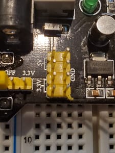
Under this power module you have two sets of pins on each side. These connect to each side of the breadboard.
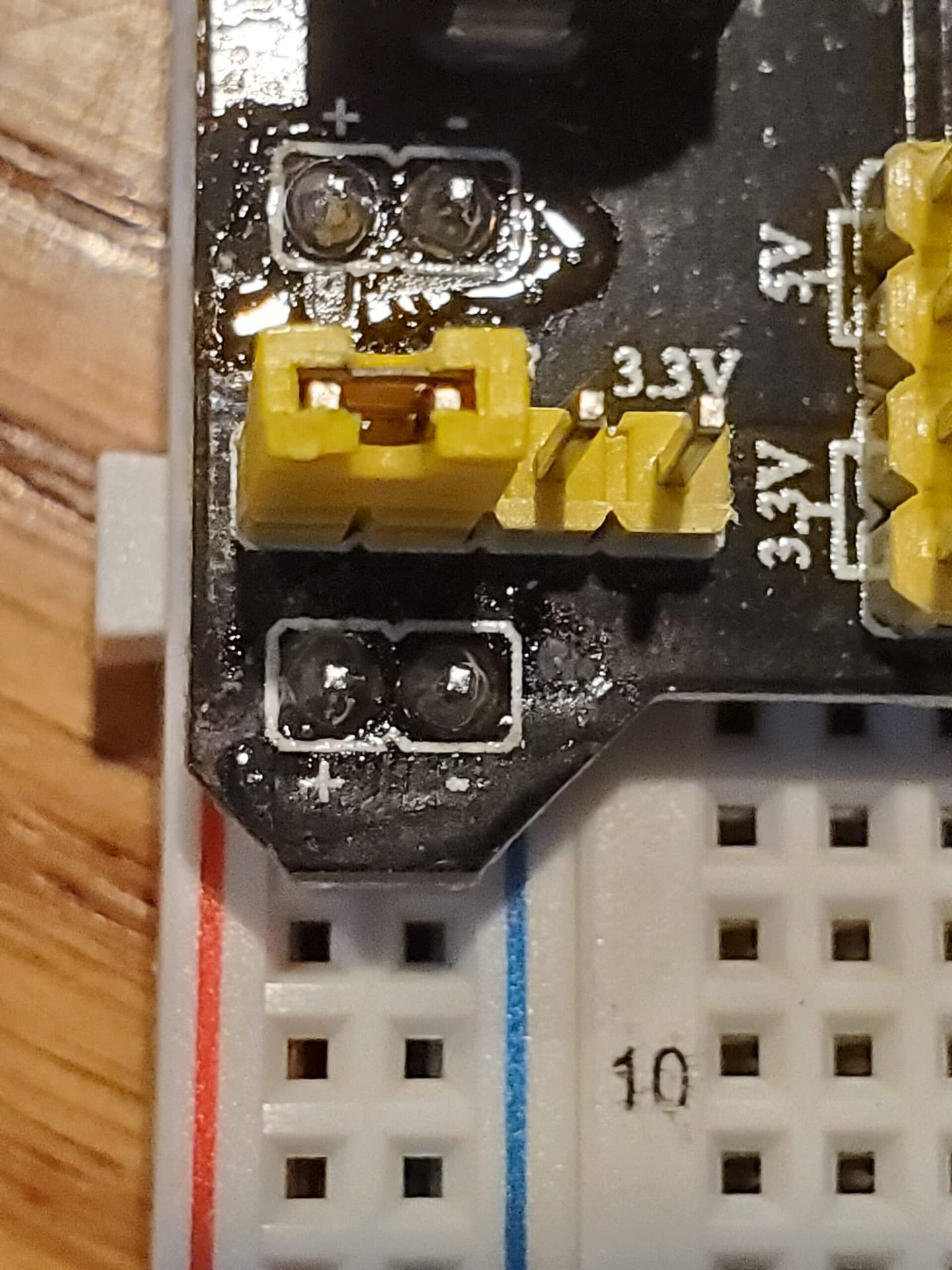
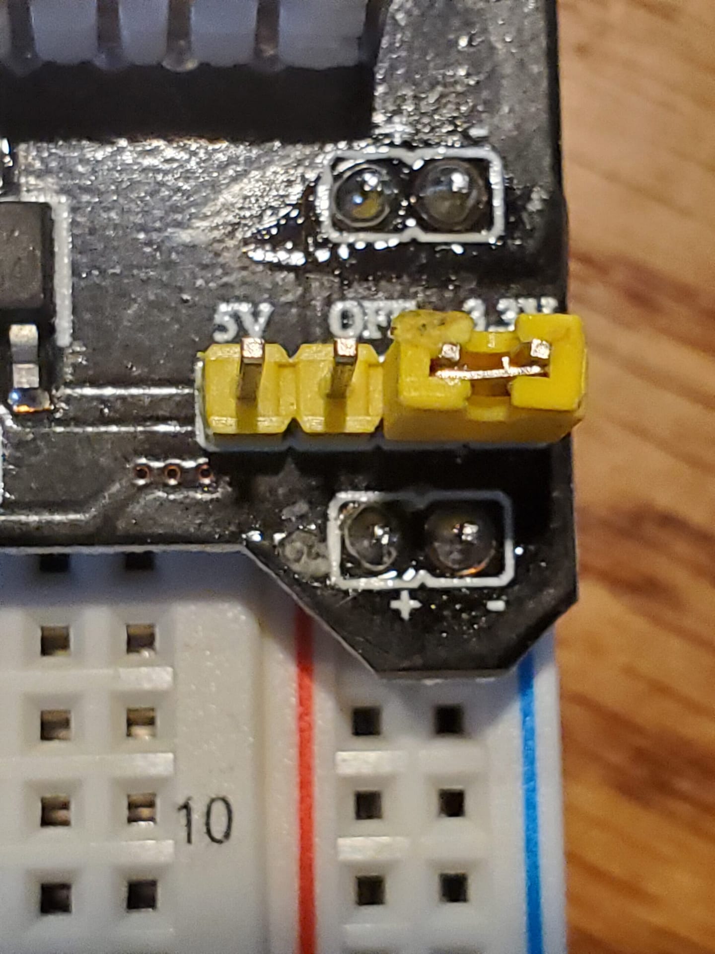
On each side of the power module. you have + and – to match up the breadboard. As you can see they match up with the red (+) and blue (-). I set the left side to 5V and right side to 3.3V to match up to the 9V power supply.
The 4 x 2 pin connectors provide 5V and 3.3V. Top left pins are 5V. Bottom left pins are 3.3V. Right side are ground pins.
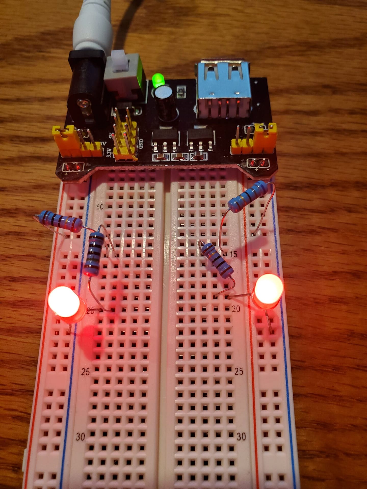
In order to test the power output. I will add two simple LED circuits.
5V – 1.8V = 3.2V / 0.020 A ≥ 160 Ω
3.3V – 1.8V = 1.5V / 0.020 A ≥ 75 Ω
On left side: 150 Ω + 10 Ω resistors for 160 Ω . Multimeter reading is 159.2 Ω.
Brown – Green – Black – Black – Brown 150 Ω: 1% tolerance or 1.50Ω.
Brown – Black – Black – Gold – Brown 10 Ω: 1 % tolerance or 0.1 Ω
Voltage below the LED : 5V by multimeter
On right side: 68 Ω + 10 Ω resistors for 78 Ω . Multimeter reading is 78.0 Ω
Blue – Gray – Black – Gold – Brown 68 Ω: 1% tolerance or .68 Ω
Brown – Black – Black – Gold – Brown 10 Ω: 1 % tolerance or 0.1 Ω