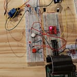
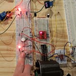
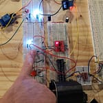
I am using the Single Supply Level Logic Converter to get 5V for this project.
We will start with the 9V battery side of the relay. Yes, I could use 120V or higher devices. 9V is safe for novices.
9V battery – 1.5V Red LED = 7.5V needs to be dissipated to save the Red LED. Red LED is known to be 1.5V @ 20mA. So 7.5V / 0.020A = 375 Ω for the minimum resistance. You have seen this on other projects of mine that I use a 470 Ω resistor for a Red LED on a 9V battery. Red button is for Red LEDs. White button is for White LEDs. pd = Pull Down and pu = Pull Up. Full code at bottom.
pd_relay_pin = 19
pd_relay = OutputDevice(pd_relay_pin, active_high=True, initial_value=False)
pu_relay_pin = 21
pu_relay = OutputDevice(pu_relay_pin, active_high=True, initial_value=False)

pu_led_red = LED(17)
pd_led_white = LED(22)
pu_button_red = Button(18, pull_up=True)
pd_button_white = Button(24, pull_up=False)
Main.py
from gpiozero import Button, LED, OutputDevice
from time import sleep

pd_relay_pin = 19
pd_relay = OutputDevice(pd_relay_pin, active_high=True, initial_value=False)
pu_relay_pin = 21
pu_relay = OutputDevice(pu_relay_pin, active_high=True, initial_value=False)

pu_led_red = LED(17)
pd_led_white = LED(22)
pu_button_red = Button(18, pull_up=True)
pd_button_white = Button(24, pull_up=False)

while True:
    if pd_button_white.is_pressed:
        print("*** Pull Up Button is pressed ***")
        pd_led_white.on()
        pd_relay.on()

    else:
        print("Pull Up Button not pressed")
        pd_led_white.off()
        pd_relay.off()

    sleep(.5)
    if pu_button_red.is_pressed:
        print("*** Pull Down Button is pressed ***")
        pu_led_red.on()
        pu_relay.on()

    else:
        print("Pull Down Button not pressed")
        pu_led_red.off()
        pu_relay.off()
sleep(.5) 


