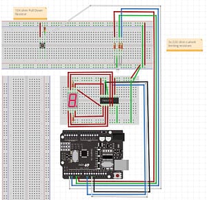
I have been reading Jeremy Blum’s Exploring Arduino. I had a RGB LED in the box. So I decided to try his code out. The only difference was the type. It was a cathode RGB LED. To get it to work, I had to take it to the ground instead of 5V. I connected it to the 4th Slave with the 7 segment LED on pins 10,11 and 13. I have cleanup work to do on the code.
/*
Exploring Arduino - Code Listing 2-6: Toggling LED Nightlight
http://www.exploringarduino.com/content/ch2
Copyright 2013 Jeremy Blum ( http://www.jeremyblum.com )
This program is free software: you can redistribute it and/or modify
it under the terms of the GNU General Public License v3 as published by
the Free Software Foundation.
*/

const int BLED=3; //Blue LED on Pin 9
const int GLED=5; //Green LED on Pin 10
const int RLED=6; //Red LED on Pin 11
const int BUTTON=2; //The Button is connected to pin 2

boolean lastButton = LOW; //Last Button State
boolean currentButton = LOW; //Current Button State
int ledMode = 0; //Cycle between LED states

#include
int LED = 13;

// 8 segment LED for x counter
int latchPin_7Segment=11; //white 595 pin 12
int clockPin_8Segment=9; //blue 595 pin 11
int dataPin_8Segment=12; //black 595 pin 14
// 8 segment LED for x counter

// i2c counter
int x = 0;
int dt=250;
// i2c counter

// 8 segment LED for x counter
byte LEDsOff=0b00000000;
byte LEDsOn=0b11111111;
byte LEDs1=0b10000000;
byte LEDs2=0b01000000;
byte LEDs3=0b00100000;
byte LEDs4=0b00010000;
byte LEDs5=0b00001000;
byte LEDs6=0b00000100;
byte LEDs7=0b00000010;
byte LEDs8=0b00000001;

byte LEDZero = 0b11111100;
byte LEDOne = 0b01100000;
byte LEDTwo = 0b11011010;
byte LEDThree = 0b11110010;
byte LEDFour = 0b01100110;
byte LEDFive = 0b10110110;
byte LEDSix = 0b00111110;
// 8 segment LED for x counter

void setup() {

pinMode (BLED, OUTPUT); //Set Blue LED as Output
pinMode (GLED, OUTPUT); //Set Green LED as Output
pinMode (RLED, OUTPUT); //Set Red LED as Output
pinMode (BUTTON, INPUT); //Set button as input (not required)

pinMode (LED, OUTPUT);
pinMode (latchPin_7Segment,OUTPUT);
pinMode (dataPin_8Segment,OUTPUT);
pinMode (clockPin_8Segment,OUTPUT);

// Start the I2C Bus as Slave on address 4
Wire.begin(4);
// Attach a function to trigger when something is received.
Wire.onReceive(receiveEvent);
}

/*
* LED Mode Selection
* Pass a number for the LED state and set it accordingly
*/
void setMode(int mode)
{
//RED
if (mode == 1)
{
digitalWrite(RLED, HIGH);
digitalWrite(GLED, LOW);
digitalWrite(BLED, LOW);
}
//GREEN
else if (mode == 2)
{
digitalWrite(RLED, LOW);
digitalWrite(GLED, HIGH);
digitalWrite(BLED, LOW);
}
//BLUE
else if (mode == 3)
{
digitalWrite(RLED, LOW);
digitalWrite(GLED, LOW);
digitalWrite(BLED, HIGH);
}
//PURPLE (RED+BLUE)
else if (mode == 4)
{
analogWrite(RLED, 127);
analogWrite(GLED, 0);
analogWrite(BLED, 127);
}
//TEAL (BLUE+GREEN)
else if (mode == 5)
{
analogWrite(RLED, 0);
analogWrite(GLED, 127);
analogWrite(BLED, 127);
}
//ORANGE (GREEN+RED)
else if (mode == 6)
{
analogWrite(RLED, 127);
analogWrite(GLED, 127);
analogWrite(BLED, 0);
}
//WHITE (GREEN+RED+BLUE)
else if (mode == 7)
{
analogWrite(RLED, 85);
analogWrite(GLED, 85);
analogWrite(BLED, 85);
}
//OFF (mode = 0)
else
{
digitalWrite(RLED, LOW);
digitalWrite(GLED, LOW);
digitalWrite(BLED, LOW);
}
}

/*
* Debouncing Function
* Pass it the previous button state,
* and get back the current debounced button state.
*/
boolean debounce(boolean last)
{
boolean current = digitalRead(BUTTON); //Read the button state
if (last != current) //if it's different...
{
delay(5); //wait 5ms
current = digitalRead(BUTTON); //read it again
}
return current; //return the current value
}

void receiveEvent(int bytes) {
x = Wire.read(); // read one character from the I2C
}
// i2c counter

void loop() {

currentButton = debounce(lastButton); //read debounced state
if (lastButton == LOW && currentButton == HIGH) //if it was pressed...
{
ledMode++; //increment the LED value
}
lastButton = currentButton; //reset button value
//if you’ve cycled through the different options, reset the counter to 0
if (ledMode == 8) ledMode = 0;
setMode(ledMode);

/*
// test all LED display
digitalWrite(latchPin_7Segment,LOW);
shiftOut(dataPin_8Segment,clockPin_8Segment,LSBFIRST,LEDsOn);
digitalWrite(latchPin_7Segment,HIGH);
delay(dt);
*/

// i2c counter
if (x == 1) {
//LED display
digitalWrite(latchPin_7Segment,LOW);
shiftOut(dataPin_8Segment,clockPin_8Segment,LSBFIRST,LEDOne);
digitalWrite(latchPin_7Segment,HIGH);
}

if (x == 2) {

digitalWrite(latchPin_7Segment,LOW);
shiftOut(dataPin_8Segment,clockPin_8Segment,LSBFIRST,LEDTwo);
digitalWrite(latchPin_7Segment,HIGH);
}

if (x == 3) {

//LED display
digitalWrite(latchPin_7Segment,LOW);
shiftOut(dataPin_8Segment,clockPin_8Segment,LSBFIRST,LEDThree);
digitalWrite(latchPin_7Segment,HIGH);
}

if (x == 4) {

digitalWrite(latchPin_7Segment,LOW);
shiftOut(dataPin_8Segment,clockPin_8Segment,LSBFIRST,LEDFour);
digitalWrite(latchPin_7Segment,HIGH);
}

if (x == 5) {
digitalWrite(LED, HIGH);
//LED display
digitalWrite(latchPin_7Segment,LOW);
shiftOut(dataPin_8Segment,clockPin_8Segment,LSBFIRST,LEDFive);
digitalWrite(latchPin_7Segment,HIGH);
}
else {
digitalWrite(LED, LOW);
}

if (x == 6) {
digitalWrite(LED, HIGH);
// i2c counter

// 8 segment LED for x counter
digitalWrite(latchPin_7Segment,LOW);
shiftOut(dataPin_8Segment,clockPin_8Segment,LSBFIRST,LEDSix);
digitalWrite(latchPin_7Segment,HIGH);
}

/*
//test rgb
digitalWrite(RLED, LOW);
delay(100);
digitalWrite(RLED, HIGH);
delay(200);

digitalWrite(GLED, LOW);
delay(100);
digitalWrite(GLED, HIGH);
delay(200);

digitalWrite(BLED, LOW);
delay(100);
digitalWrite(BLED, HIGH);
delay(200);
*/

}
