I decided to expand my test lab to do more EE work with the Arduino and Raspberry Pi devices along with building new and interesting circuits. I have been researching the components to build a proper test lab.
1. Oscilloscope
2. Frequency Generator for Sine, Square and Triangle waves
3. Bench Power Supplies
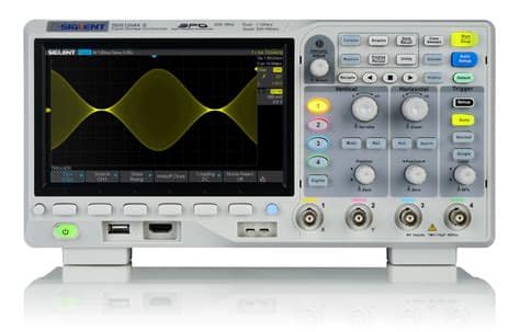
I was looking at the Rigol DS1054-Z 50 Mhz 4 channel scope for $359. The price jumped to $419 and it wasn’t available on many sites like Digikey. Siglent came to market to compete with Rigol on 4 channel scopes. The SDS-1104X-E is a 100 Mhz scope that is 4 channel. Tequipment had it for $482 instead of the $499 base price. It has a nicer screen. It received good reviews on quality and performance. I have been researching the workstation software and firmware upgrades. I watched the videos on tuning the probes. More on the Oscilloscope page.
I ordered a Siglent SDS-1104X-E 100 Mhz, 4 channel Oscilloscope with LAN.
Bandwidth: 100 MHz
Channels: 4
Real time sampling rate: 1 GSa/s (Total of 2 A-to-D converters)
Maximum capture rate: (100,000 in Normal mode, 400,000 in Sequence mode)
Memory depth: 14 Mpts
Bode Plot function (Requires SIGLENT SDG X or SAG1021 function generator)
Search / Navigate functions
Web-Based browser remote control
Optional Wi-Fi dongle
Optional MSO capability
The Siglent SDS1104X-E Oscilloscope arrived. I let it sit in the packing box for 6 hours to acclimatize to the house. It is winter in Michigan and below 20F. I unpacked the box and pulled out the Siglent and 4 probes. I set up the probes with the four color bands yellow, pink, blue and green. Two colors on the probe BNC base and tip. I connected it to the Gigabit switch by my desk. I setup DHCP on the Fortinet to give it an address of 10.10.10.100. I checked the firmware release and upgraded it to the latest on Siglent’s site. I tend to upgrade all hardware, when I first get it. I plugged in the scope and started to compensate the scope and probes. I need to redo it because I forgot to change the probes to 1x. They should be close. First thing I looked up was how to change each channel to 10X on the scope. I plan on posting write ups on how to do the firmware, IP setup, and change the channels.
So I started by unboxing the Siglent and sorting out the probes. The first thing is put the plastic bands in the kit on each probe base and tip to match the 4 channels. You will calibrate the probes for each channel. Each probe comes with all the colored rights and a screw driver for calibrating the probe. I put the other rings back into the proper bag for each probe. The probe must be set to 10x to turn the calibration screw not 1x.
Siglent PP510 100MHz 1X/10X attenuation, 85/18pf, 1M/10Mohm, 6M/70MHz, 300V/600V, operating temperature -15 to 75 degrees probe
So the probe: 1x is 6 MHz and 10x is 70-100 MHz
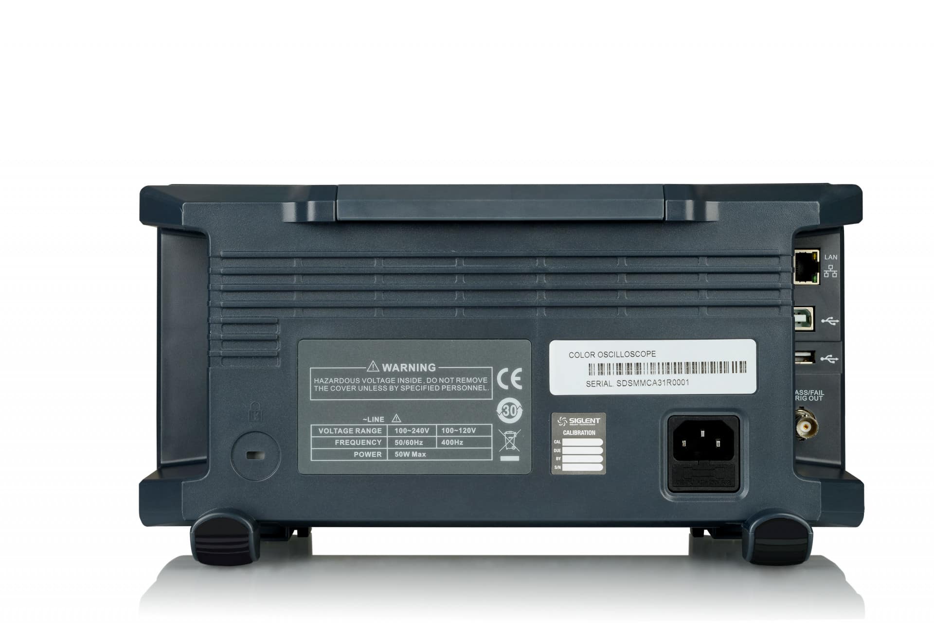
Networking:
I connected the network cable from my gigabit switch to the NIC Port on the back. I didnt find a wireless dongle mentioned in some of the videos. Many state the direct connect is faster. I went into the network interface and found the mac address. I setup a reserved IP on my Fortinet firewall for the Siglent as 192.168.1.200. I am planning on installing their desktop software to control the scope. It would have been interesting to connect it up IPv6. The first task is to get your oscilloscope onto your network. Plug the LAN port into a switch or router, and navigate to Utility -> I/O -> IP Set. Then use the soft button to toggle the DHCP Field from “Disabled” to “Enabled.” The scope should then pull an IP address from your router. For now, I put the DHCP reservation on my Fortinet.
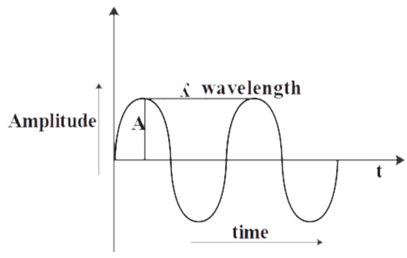
1 kHz = 1000 Hz
1/ 0.001 seconds = 1000 Hz = 1 = (0.001 seconds )(1000/seconds)
Think of is as 1000 Hz give you a period of 1 ms.
100 Hz is a period of 10 ms 1/0.010 seconds = 100 Hz.
Generally, scopes will feature around 8-10 vertical (voltage) divisions, and 10-14 horizontal (seconds) divisions. Older scopes (especially those of the analog variety) usually feature a simple, monochrome display, though the intensity of the wave may vary.
Starting Configuration and Setup
I started by upgrading the firmware of the scope. I downloaded the latest EasyScopeX Windows 11 software for my workstation. You can run the entire scope from your workstation and copy output for the web site. You will unpack all four probes and place the color rings on each one corresponding to the four channels: Yellow, Purple, Blue, Green. Each probe is slightly different. You want to set each channel and probe to 10x. Press the channel button 1 to 4. You will see a setup that has Probe 1x. You use the intensity/adjustment knob above channel 1 to change it to match the 10x switch on the probe. You follow the guide for probe compensation
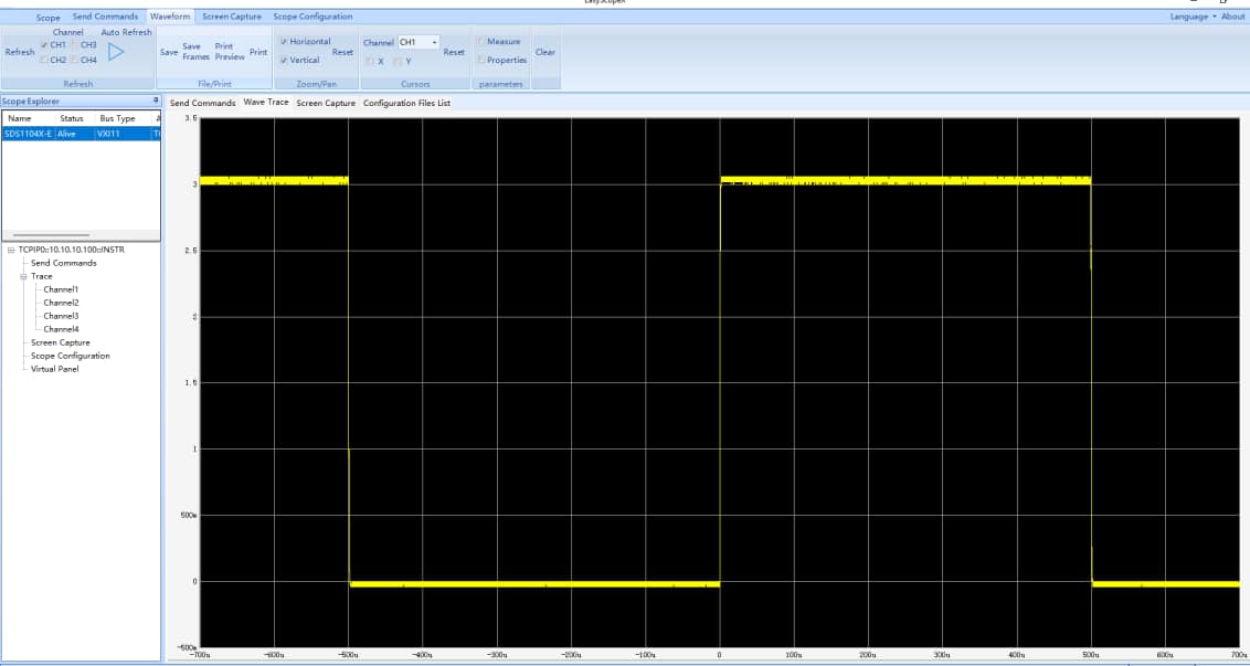
The two metal posts in the picture below are used to for probe compensation. The ground goes on the right and lead goes on the left. You will get a 1kHz signal that is 1.5V. You follow the guide to set the square wave properly on the screen. You use the non-metalic driver to set the probe screw. The tool is in the bag with the probe.
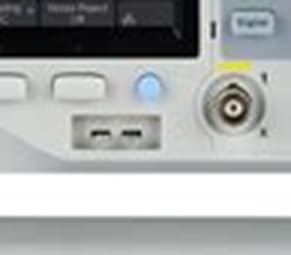
You adjust the screw till the wave to flat. My probes usually have issues on the leading edge. The signal is 3V in height and from -500us to 500us or 1000us (1ms). The signal isn’t perfectly 3V pk-pk. The max is 1.06V and min is -0.040V. The frequency is reading 1kHz. This is what you get for a $500 scope. You want more accuracy buy a better scope and probes, $2000+.

Setting up the network for EasyScopeX
Click on utility. get to page 2 of 4. Click on I/O. Configure either DHCP or Static IPv4 address. You will need to install the NI-VISA software and EasyScopeX.
Using EasyScopeX Software to retrieve Average Waveform Data
Initial Setup
– Download NI-VISA Runtime Engine that matches your operating system, if your computer does not already have the VISA library.
It can be downloaded from National Instruments: http://bit.ly/2pw5gQW
– VISA library installed. This is the communication library used by EasyScope X software to communicate with the instrumentation
– Download EasySpectrum Software from the SSA3000X Product Page on the SIGLENT America website: http://bit.ly/2okc8wG
The Arduino and Raspberry Pi are DC voltage.