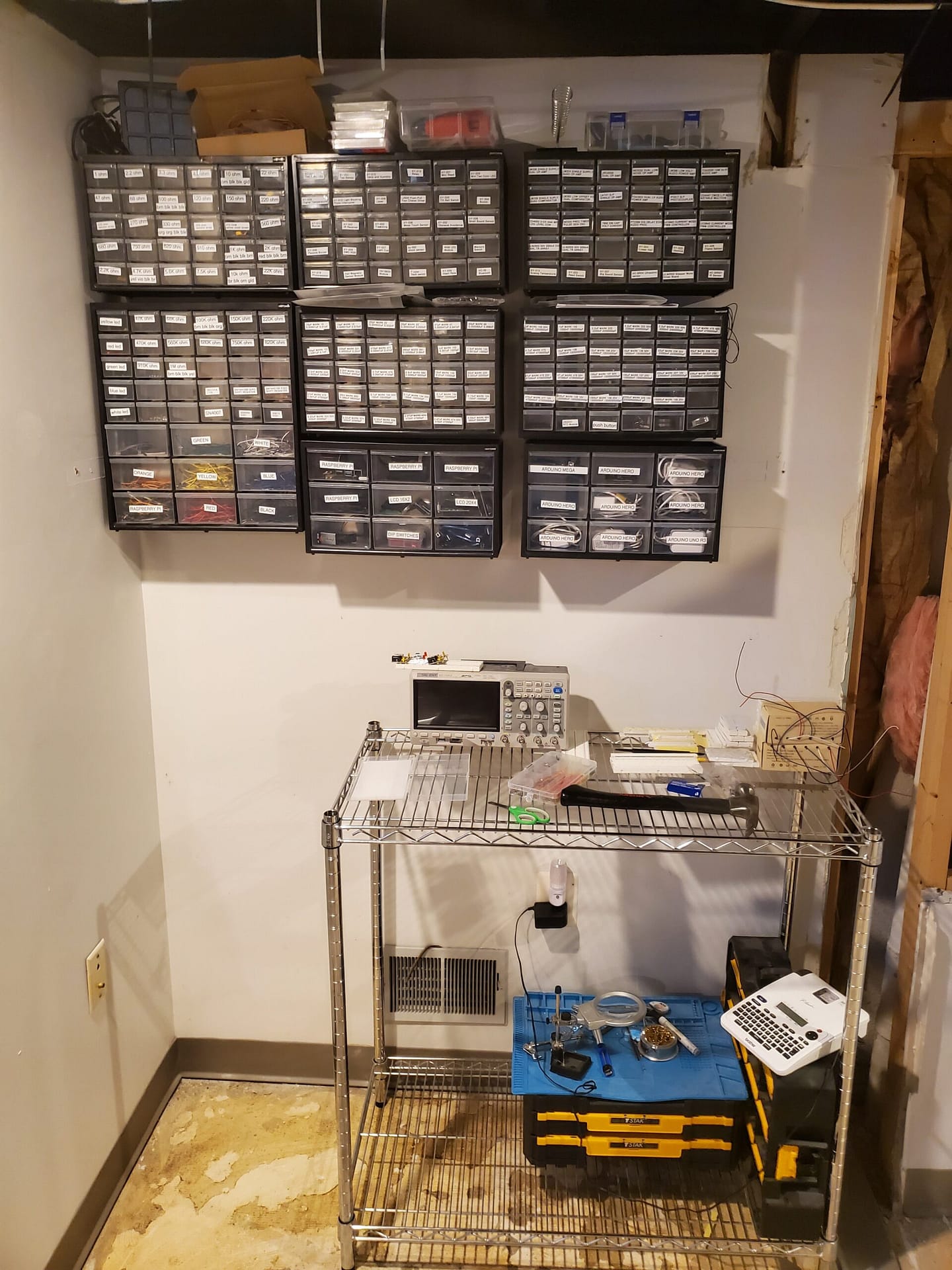
Wow! The just opened. Standing outside is my crew. I now have access to my spart parts lab.

#include <Arduino.h> uncomment if using IDE other than Arduino.  I have a Raspberry PI that I will be using with Arduino IDE.
/*
array for crew
1      1701796041     Capt.   Douglas     Adams     AA    B3    3C    29
2      23715925245    Lt.     Ford        Prefect   ED    9F    FC    2D
# 3    2027724463     Sgt.    Authur      Dent      CA    4D    F4    3F  //Returned with damaged RFID
4      162814481      Eng.    Kieran      McKenney  A2    51    2C    51
5      16711203167    Blank   Blank       Blank     A7    0B    CB    A7
# 6    18358204167    Blank   Blank       Blank     B7    3A    CC    A7  //Returned with damaged RFID

    String crew[rows][columns] = { { "1", "1701796041", "Capt.", "Douglas", "Adams", "AA", "B3", "3C", "29", "Granted"},
                                   { "2", "23715925245", "Lt.", "Ford", "Prefect", "ED", "9F", "FC", "2D", "Granted" },
                                   { "3", "", "", "", "", "", "", "", "", "" },
                                   { "4", "162814481", "Eng.", "Kieran", "McKenney", "A2", "51", "2C", "51", "Granted" },
                                   { "5", "16711203167", "", "", "", "A7", "0B", "CB", "A7", "Denied"},
                                   { "6", "", "", "", "", "", "", "", "", ""} };
*/

#include <SPI.h>
#include <MFRC522.h>
#include <Wire.h>  // Library for I2C Wire

// C++ creates class objects.  The class is LiquidCrystal_I2C.  Each LCD has its own class based on its address.

#include <LiquidCrystal_I2C.h> // Library for I2C LCD displays
LiquidCrystal_I2C lcd_20(0x20, 20, 4); // I2C address 0x20, 20 column and 4 rows
LiquidCrystal_I2C lcd_21(0x21, 20, 4); // I2C address 0x21, 20 column and 4 rows
LiquidCrystal_I2C lcd_22(0x22, 20, 4); // I2C address 0x22, 20 column and 4 rows
LiquidCrystal_I2C lcd_23(0x23, 20, 4); // I2C address 0x23, 20 column and 4 rows
LiquidCrystal_I2C lcd_24(0x24, 20, 4); // I2C address 0x24, 20 column and 4 rows
LiquidCrystal_I2C lcd_25(0x25, 20, 4); // I2C address 0x25, 20 column and 4 rows
LiquidCrystal_I2C lcd_26(0x26, 20, 4); // I2C address 0x25, 20 column and 4 rows
LiquidCrystal_I2C lcd_27(0x27, 20, 4); // I2C address 0x25, 20 column and 4 rows

/* Typical pin layout used:
 * -----------------------------------------------------------------------------------------
 *             MFRC522      Arduino       Arduino   Arduino    Arduino          Arduino
 *             Reader/PCD   Uno/101       Mega      Nano v3    Leonardo/Micro   Pro Micro
 * Signal      Pin          Pin           Pin       Pin        Pin              Pin
 * -----------------------------------------------------------------------------------------
 * RST/Reset   RST          9             5         D9         RESET/ICSP-5     RST
 * SPI SS      SDA(SS)      10            53        D10        10               10
 * SPI MOSI    MOSI         11 / ICSP-4   51        D11        ICSP-4           16
 * SPI MISO    MISO         12 / ICSP-1   50        D12        ICSP-1           14
 * SPI SCK     SCK          13 / ICSP-3   52        D13        ICSP-3           15
 *
 */

#define SSPin 53//define sda pin
#define RSTPin 49 //define reset pin
#
//Cabin Light
// #define SwitchPin_22 22
#define RedLed_22 22
#define SwitchPin_23 23

//Opening Front View
#define WhiteLed_24 24
#define SwitchPin_25 25


//Opening Rear View
#define BlueLed_26 26
#define SwitchPin_27 27


int redPin = 8; //pin connected to red cathode of RGB LED
int greenPin = 9; //pin connected to green cathode of RGB LED
int bluePin = 10; //pin connected to blue cathode of RGB LED
int IntRC[4]; // This converts the key fob ID to integers
int Dly = 5000;

String readCard[4]; //array for storing the UID of the card, 4 is the size because it will store 4 hexadecimal values but convert to string for easy identity checking later on

MFRC522 mfrc522(SSPin, RSTPin); //create instance of mfrc522 class
MFRC522::MIFARE_Key key;        //create key structure used to store card info

//custom color writer func for rbg led
void RGBColorPicker(int redValue, int greenValue, int blueValue) { //3 parameters, red, green, blue value are used for writing the different color values to make a single color to display on the LED
  analogWrite(redPin, redValue); //write specific value for red aspect of the RGB LED
  analogWrite(greenPin, greenValue); //write specific value for green aspect of the RGB LED
  analogWrite(bluePin, blueValue); //write specific value for blue aspect of the RGB LED

}

//reads card uid stores in string
String readCardUID(String UIDToRead) { //parameter: UIDToRead used to pass a string in which we want to store the UID
  for (int i = 0; i < mfrc522.uid.size; i++){ // create a loop to go through the UID, for which the end of the reading is defined by the size
    readCard[i] = String(mfrc522.uid.uidByte[i]); //mfrc522.uid.uidByte = an array containing the entire uid for our card but we can only take it out one byte at a time; convert to string so we can store it in our redCard array
    IntRC[i] = readCard[i].toInt();
    UIDToRead = UIDToRead + readCard[i]; //continuously concatanate the read byte into our passed string, UIDToRead
  }
  return(UIDToRead);
}

void setup() {
  // Arduino Mega on I2C Bus
  // I usually connect my Arduino devices and Raspberry Pi devices to the I2C bus.  This will start the addresses at 0x50.
  Wire.begin(0x50);

  //DIP Switch for Cabin Light
  pinMode(RedLed_22, OUTPUT);
  pinMode(SwitchPin_23, INPUT);

  pinMode(WhiteLed_24, OUTPUT);
  pinMode(SwitchPin_25, INPUT);

  pinMode(BlueLed_26, OUTPUT);
  pinMode(SwitchPin_27, INPUT);


  //DIP Switch for Opening

  // I2C LCD screens are on addresses 0x20 to 0x27.  This code is used to find all of the I2C LCDs attached.
  lcd_20.clear();   // clear display 0x20
  lcd_20.init(); // initialize the lcd
  lcd_20.backlight();
  lcd_20.setCursor(0, 0);
  lcd_20.print("0x20");

  lcd_21.clear();   // clear display 0x21
  lcd_21.init(); // initialize the lcd
  lcd_21.backlight();
  lcd_21.setCursor(0, 0);
  lcd_21.print("0x21");

  lcd_22.clear();   // clear display 0x22
  lcd_22.init(); // initialize the lcd
  lcd_22.backlight();
  lcd_22.setCursor(0, 0);
  lcd_22.print("0x22");

  lcd_23.clear();   // clear display 0x23
  lcd_23.init(); // initialize the lcd
  lcd_23.backlight();
  lcd_23.setCursor(0, 0);
  lcd_23.print("0x23");

  lcd_24.clear();   // clear display 0x24
  lcd_24.init(); // initialize the lcd
  lcd_24.backlight();
  lcd_24.setCursor(0, 0);
  lcd_24.print("0x24");

  lcd_25.clear();   // clear display 0x25
  lcd_25.init(); // initialize the lcd
  lcd_25.backlight();
  lcd_25.setCursor(5, 0);         // move cursor to   (5, 0)
  lcd_25.print("Welcome To");
  lcd_25.setCursor(4, 1);         // move cursor to   (4, 1)
  lcd_25.print("The Heart of");
  lcd_25.setCursor(3, 2);         // move cursor to   (3, 2)
  lcd_25.print("Stainless Steel");

  lcd_26.clear();   // clear display 0x26
  lcd_26.init(); // initialize the lcd
  lcd_26.backlight();

  // 0x27 is in use with the RFID tagging system.
  lcd_27.clear();   // clear display 0x27
  lcd_27.init(); // initialize the lcd 0x27
  lcd_27.backlight();

  //define RGB LED outputs
  pinMode(redPin, OUTPUT);
  pinMode(greenPin, OUTPUT);
  pinMode(bluePin, OUTPUT);

  RGBColorPicker(0,0,255); //initialize our RGB LED at color blue
  SPI.begin(); //begin SPI bus

  mfrc522.PCD_Init(); //initialize mfrc522 card
  for (byte i = 0; i < 6; i++){
    key.keyByte[i] = 0xFF; //set key security id values to 0xFF across the board
  }
        lcd_27.setCursor(0, 0);         // move cursor to   (0, 0)
        lcd_27.print("Scan ");        // print message at (0, 0)
}

void loop() {

    // I usually use arrays for data groups.  This group is the RFID information, rank and crew members.
    int rows = 6;
    int columns = 10;
    String crew[rows][columns] = { { "1", "1701796041", "Capt.", "Douglas", "Adams", "AA", "B3", "3C", "29", "Granted"},
                                   { "2", "23715925245", "Lt.", "Ford", "Prefect", "ED", "9F", "FC", "2D", "Granted" },
                                   { "3", "", "", "", "", "", "", "", "", "" },
                                   { "4", "162814481", "Eng.", "Kieran", "McKenney", "A2", "51", "2C", "51", "Granted" },
                                   { "5", "16711203167", "", "", "", "A7", "0B", "CB", "A7", "Denied"},
                                   { "6", "", "", "", "", "", "", "", "", ""} };


//DIP Switch for cabin light
if (digitalRead(SwitchPin_23) == HIGH)
      {
        lcd_26.setCursor(0, 0);
        lcd_26.print("Cabin Light is  ON");
        digitalWrite(RedLed_22, HIGH);

      }

if (digitalRead(SwitchPin_23) == LOW)
      {
        lcd_26.setCursor(0, 0);
        lcd_26.print("Cabin Light is OFF");
        digitalWrite(RedLed_22, LOW);

      }

//DIP Switch for opening front view
if (digitalRead(SwitchPin_25) == HIGH)
      {
        digitalWrite(WhiteLed_24, HIGH);
        lcd_26.setCursor(0, 1);
        lcd_26.print("Front View    Open");
      }
      else
      {
        digitalWrite(WhiteLed_24, LOW);
        lcd_26.setCursor(0, 1);
        lcd_26.print("Front View  Closed");
      }

//DIP Switch for opening rear view
if (digitalRead(SwitchPin_27) == HIGH)
      {
        digitalWrite(BlueLed_26, HIGH);
        lcd_26.setCursor(0, 2);
        lcd_26.print("Rear View    Open");
      }
      else
      {
        digitalWrite(BlueLed_26, LOW);
        lcd_26.setCursor(0, 2);
        lcd_26.print("Rear View  Closed");
      }

  String UID = ""; //first read
  String SecondRead = ""; //second read

  // if new card is not present rerun loop
  if (!mfrc522.PICC_IsNewCardPresent()){
    return;
  }

  //select card to read
  if (!mfrc522.PICC_ReadCardSerial()){
    return;
  }


  UID = readCardUID(UID); //call the readCardUID function and store it in UID variable
  for ( int i = 0; i <= 6; i++ ) {

       RGBColorPicker(0,0,255);  //Start RGB LED as Blue
    if ( UID == crew[i][1]){
        //print to I2C LCD 0x27 UID on line 1
        lcd_27.clear();                 // clear display
        lcd_27.setCursor(0, 0);         // move cursor to   (0, 0)
        lcd_27.print("UID: ");        // print message at (0, 0)
        lcd_27.setCursor(5, 0);         // move cursor to   (5.0)
        lcd_27.print(UID); // print message at (2, 1)

        lcd_27.setCursor(0, 1);         // move cursor to   (0, 1)
        lcd_27.print(crew[i][2]);        // print message at (0, 1)
        lcd_27.print(" ");
        lcd_27.print(crew[i][3]);        // print message at (0, 1)
        lcd_27.print(" ");
        lcd_27.print(crew[i][4]);

        lcd_27.setCursor(0, 2);         // move cursor to   (0, 2)
        lcd_27.print("Access: ");
        lcd_27.setCursor(9, 2);         // move cursor to   (9, 2)
        lcd_27.print(crew[i][9]);

         // This code changes the RGB LED to colors depending on access.
         // Red for Denied
         // Green for Granted
         // I created two If Else statements that do the same thing.  The active one is less code.
         /*
         if (crew[i][9] == "Granted")
            {
            // RGBColorPicker(0,255,0); //set color to green
            RGBColorPicker(0,255,0);
            delay(Dly);
            }

          else if (crew[i][9] == "Denied")
            {
            // RGBColorPicker(0,255,0); //set color to red
            RGBColorPicker(255,0,0);
            delay(Dly);
            }
          */

          if (crew[i][9] == "Granted")
            {
            // RGBColorPicker(0,255,0); //set color to green
            RGBColorPicker(0,255,0);
            delay(Dly);
            }

          else {
          // RGBColorPicker(0,255,0); //set color to red
            RGBColorPicker(255,0,0);
            delay(Dly);
          }


    }


    lcd_27.clear();   // clear display
    //Serial.println("Scan card for message: "); //scan card for secret message
    //delay(500);
    //revealMessage(SecondRead); //calls revealMessage function, storing the second read of the UID into variable SecondRead
  }   //end of for loop

    mfrc522.PICC_HaltA(); //stops reading

  lcd_27.setCursor(0, 0);         // move cursor to   (0, 0)
  lcd_27.print("Scan: "); //end of loop -> prompts user to scan again
  RGBColorPicker(0,0,255);
}
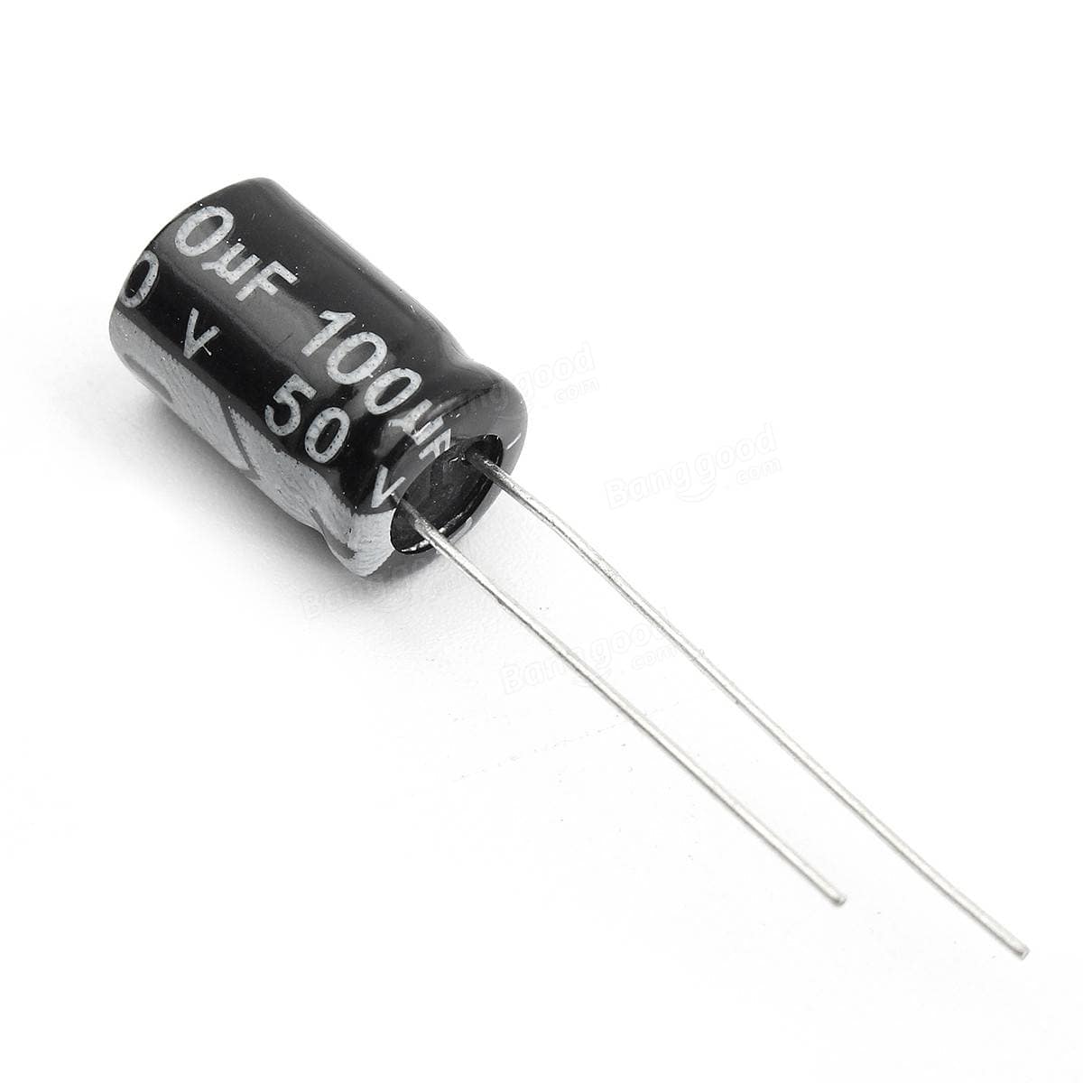
I found noise on the I2C bus that is caused by the grounding. I will place a 100uF capacitor across the VCC to Ground and I2C SDA to SCL buses. This will help clean up the noise and boost current to the circuit.