Day 1
I am Captain Douglas Adams of the Starship Heart of Stainless Steel. Our ship suffered today from a meteor shower and crashed on a planet. I can’t open the screens to find out where are. The cabin door from the command deck is not opening. I found my old computer with a very old operating system on it and my parts box. First project will be fixing the door controller. In my kit is an Arduino Mega 2560, RFID DC522 reader, some key fobs and key cards. A bundle of other components. So lets get started.
Fixing the door controller
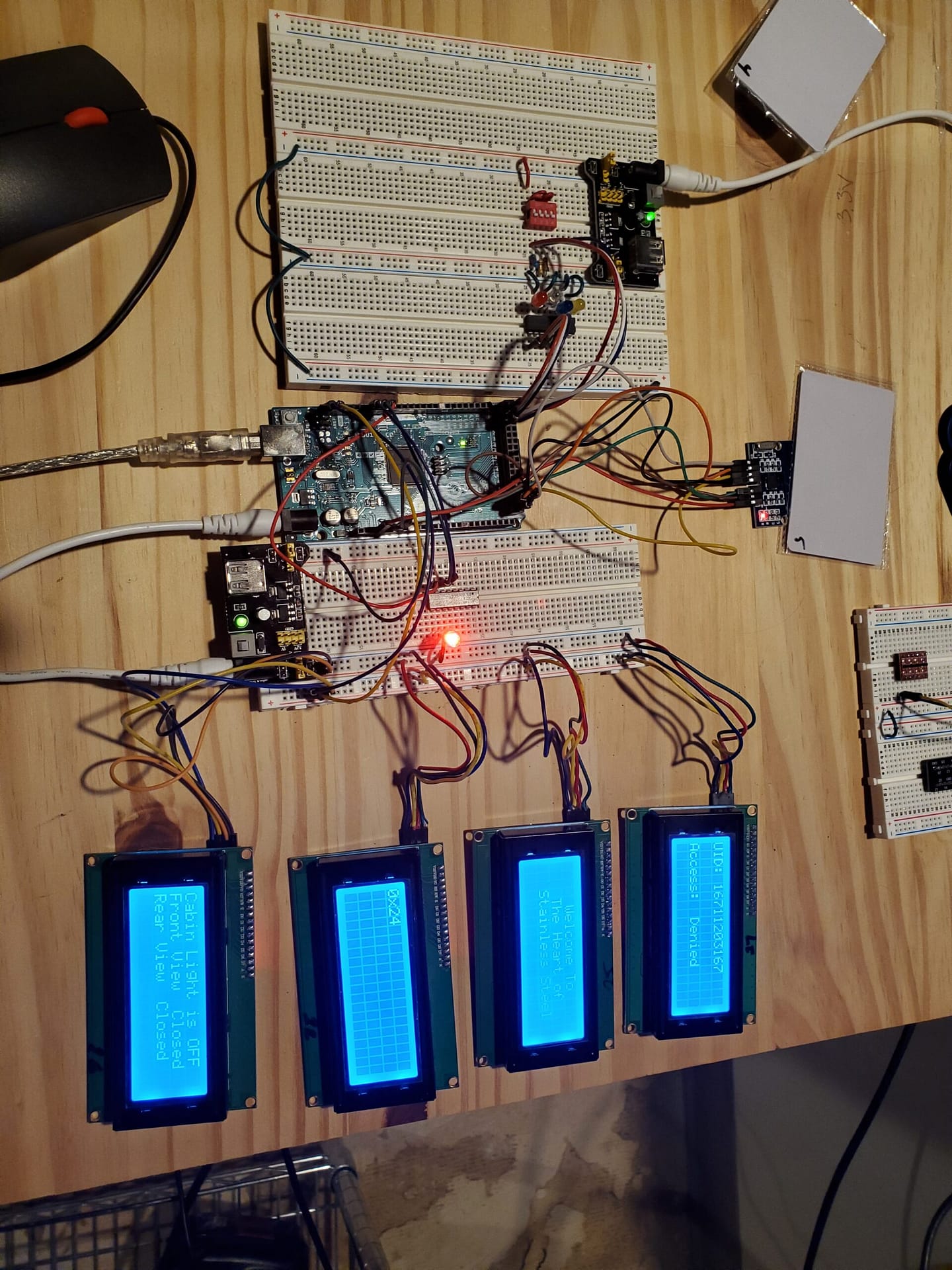
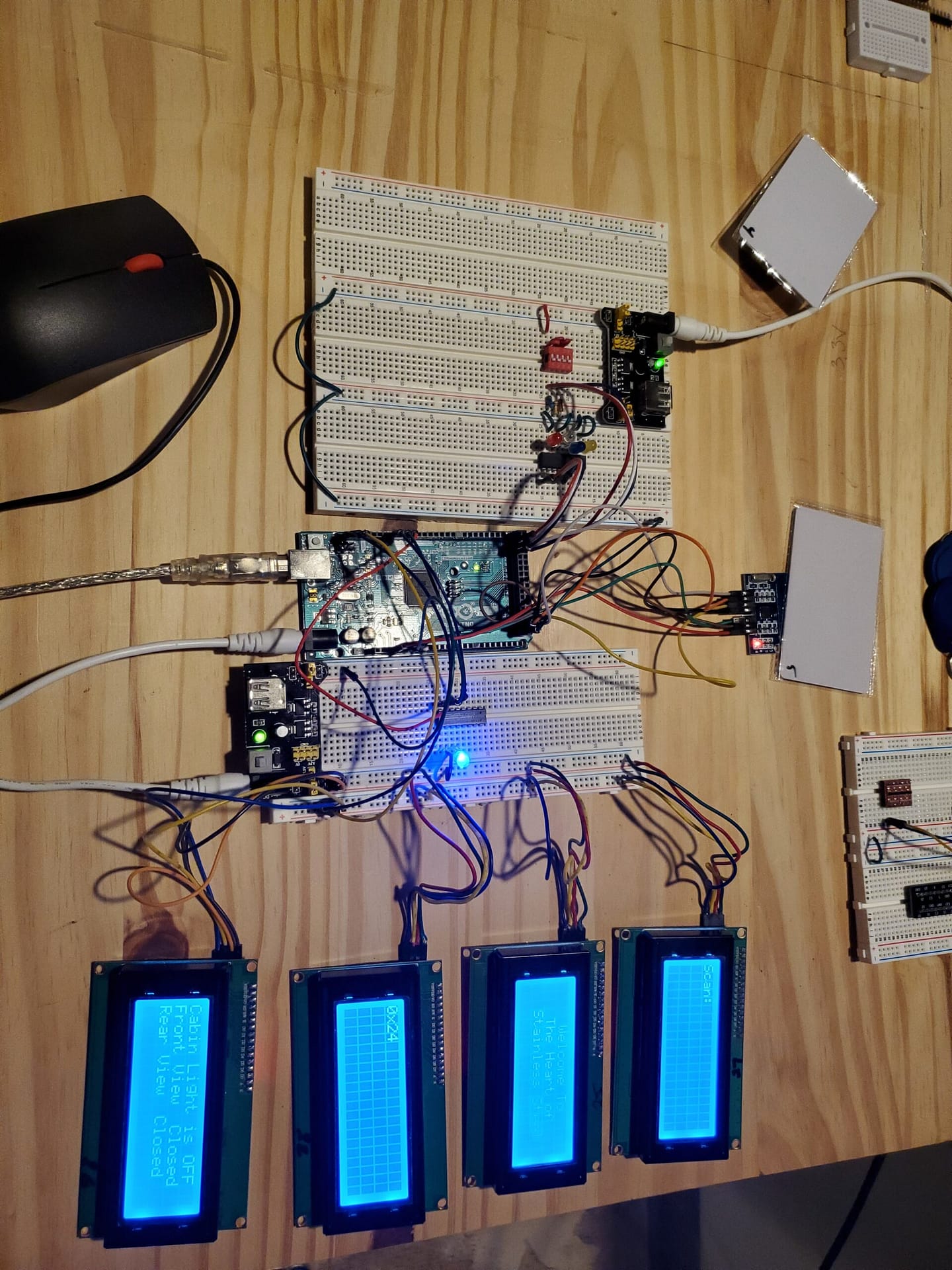
The key fobs and key cards are now labelled 1 to 6. The RFID RC522 is connected to the Arduino Mega board. In the kit were two I2C LCD screens. They are connected to the I2C bus. The kit contained two old style 9V 1A power supplies and some bread board power supplies (BBPS). I set the BBPS to 5V and 3.3V. To see what is going on, I rigged up a RGB LED and a 220 Ω resistor array.
Arduino MEGA 2560
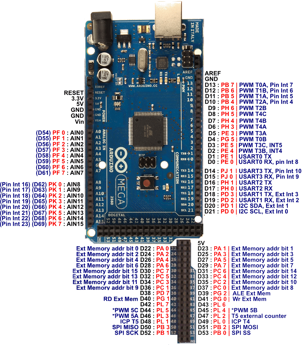
WOW! Look at the Arduino Mega 2560. It has many pins to create circuits with. I can rig up some LEDs later for lighting with switches. It has a jack for the 9V 1A power supply. I can get 700mA from it.
Where to start?
In my kit was a flash light and some batteries. At least, I can see what is going on. The instruments are dead. No lights in the command deck. My crew is banging on the door. First thing is open the door controller panel and see what I can do. Well, its fried! I can salvage some of the components.
What is a resistor array?
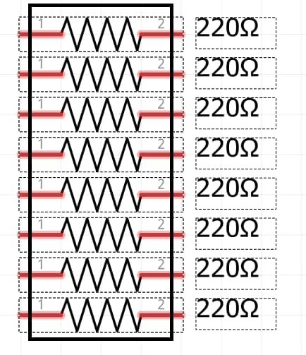
Inside the package is 8 resistors in a column. Instead of using 3 x 220 Ω resistors for the RGB LED, I use one of these IC chips.
What is an RGB LED?

An RGB LED is a fancy 3 color LED that uses 0-255 per LED to create colors. 16,777,216 colors are possible. Red is (255,0,0), Blue is (0,0,255), Lime(Green) is (0,255,0). Common Anode is the ground. You put it to the ground bar.
Let’s build the open controller circuit and program the RFID fobs and cards
RFID-RC522
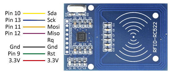
This device will be perfect for the command deck door circuit. I can program the code for the 3 key fobs for my crew and three extra key cards.
BBPS: Bread Board Power Supply
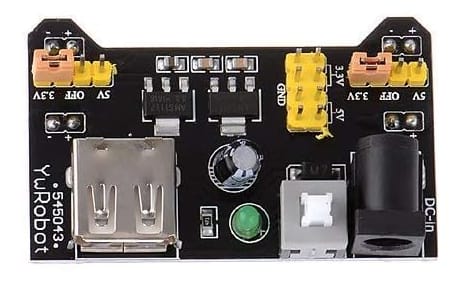
WOW! my parts kits gets better and better. This nifty device is a bread board power supply. Capable of 700mA output. I can program either side of the breadboard to 3.3V or 5V. It has a white on/off switch.
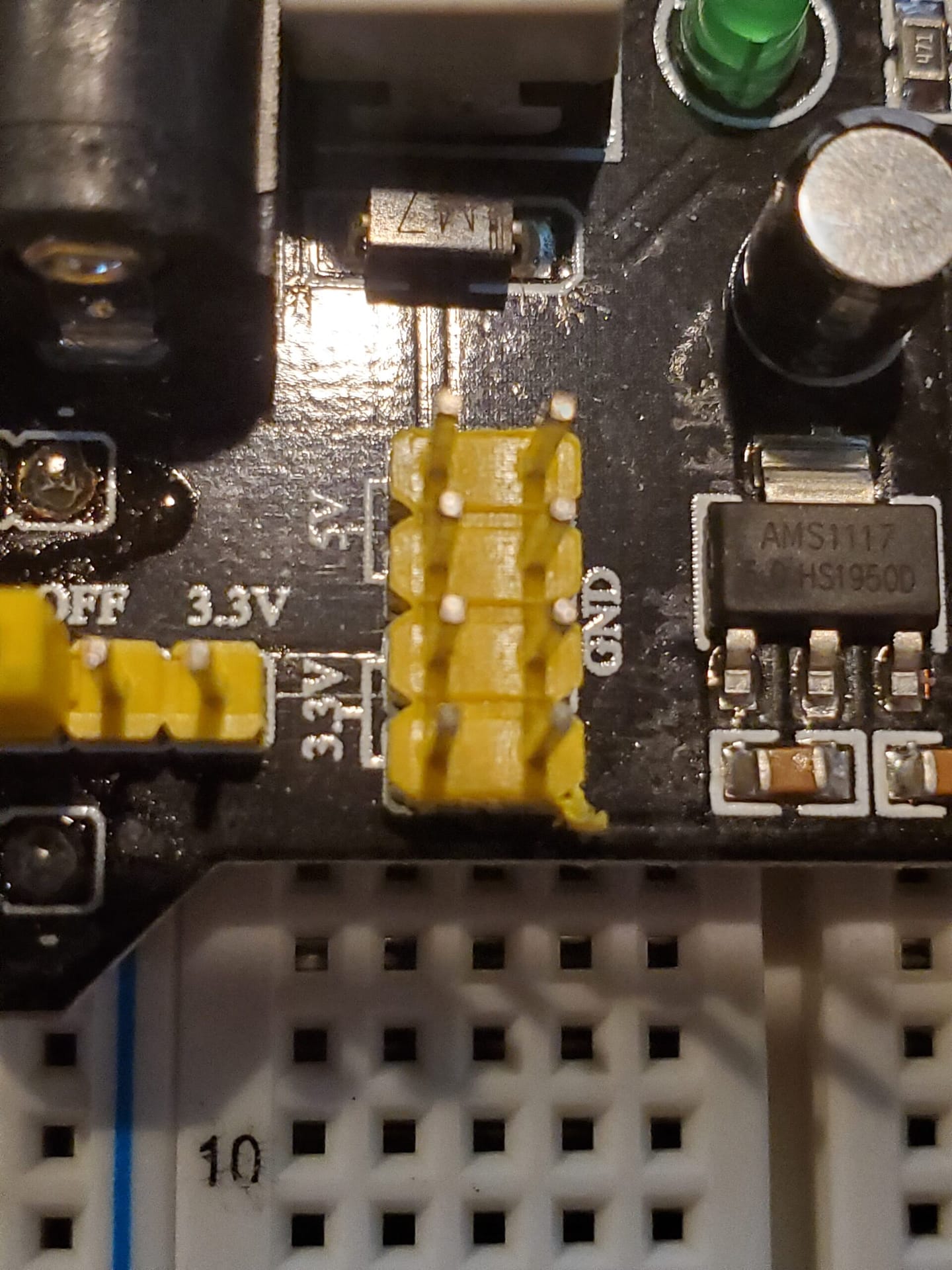
These jumpers have 3.3V and 5V along with ground pins for output devices.
I2C LCD 20×4
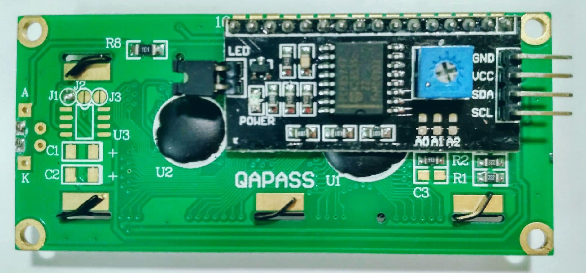
The I2C LCD 20×4 device has 4 pins. I2C bus pins SDA (Data) and SCL (Clock). The other two pins are VCC (5V) and Ground. It takes less wiring than a standard LCD. The coding is more elegant.
Let’s start building
You look closely at the first picture, you see a second row of bus pins. I added them for the I2C bus.
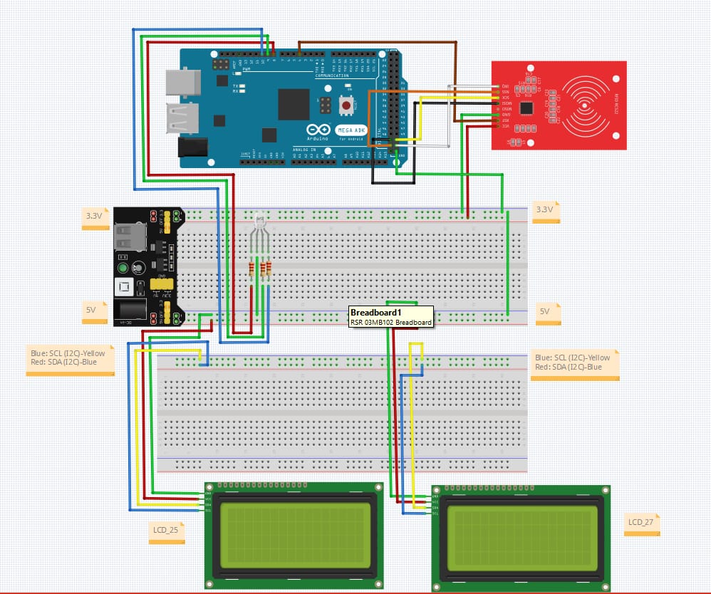
I took my design and built it in Fritzling. I know many users wants schematics. Fritzling didn’t allow me to cut the bus connector from the second breadboard. I will be creating a Fritzling breadboard design with the second row.
#include <Arduino.h> uncomment if using IDE other than Arduino. I have a Raspberry PI that I will be using with Arduino IDE.
/*
array for crew
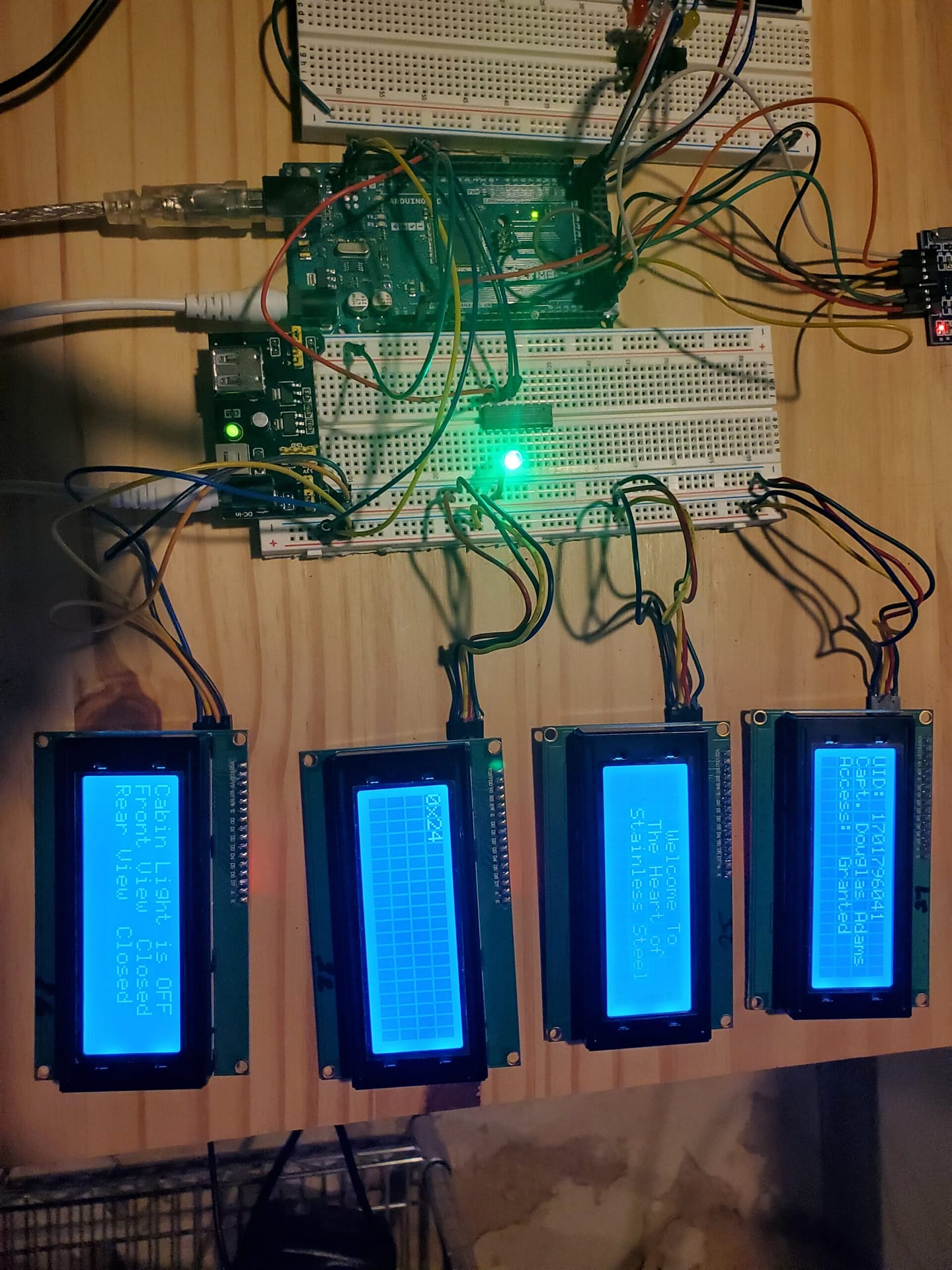
1 1701796041 Capt. Douglas Adams AA B3 3C 29 Granted
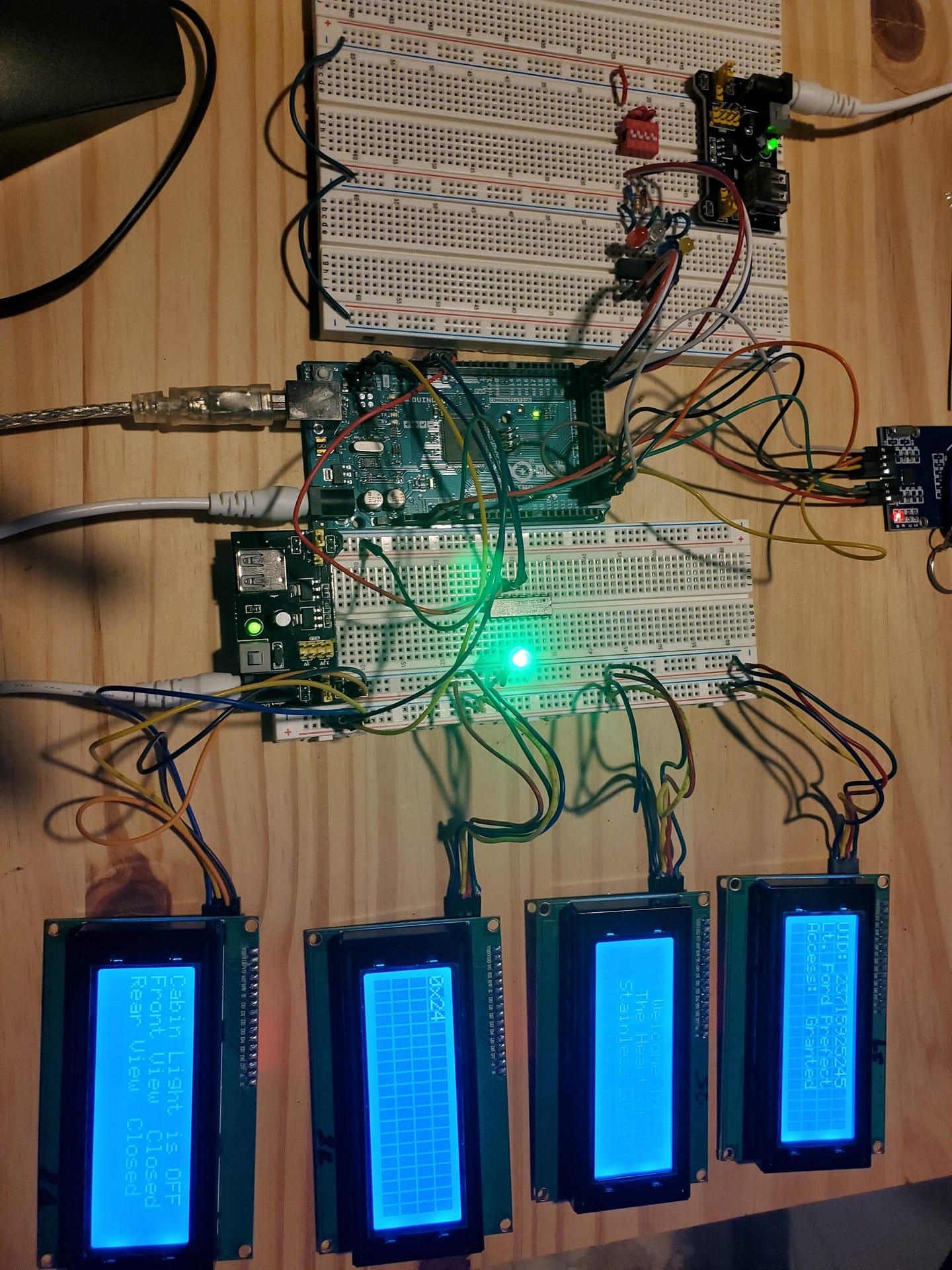
2 23715925245 Lt. Ford Prefect ED 9F FC 2D Granted
3
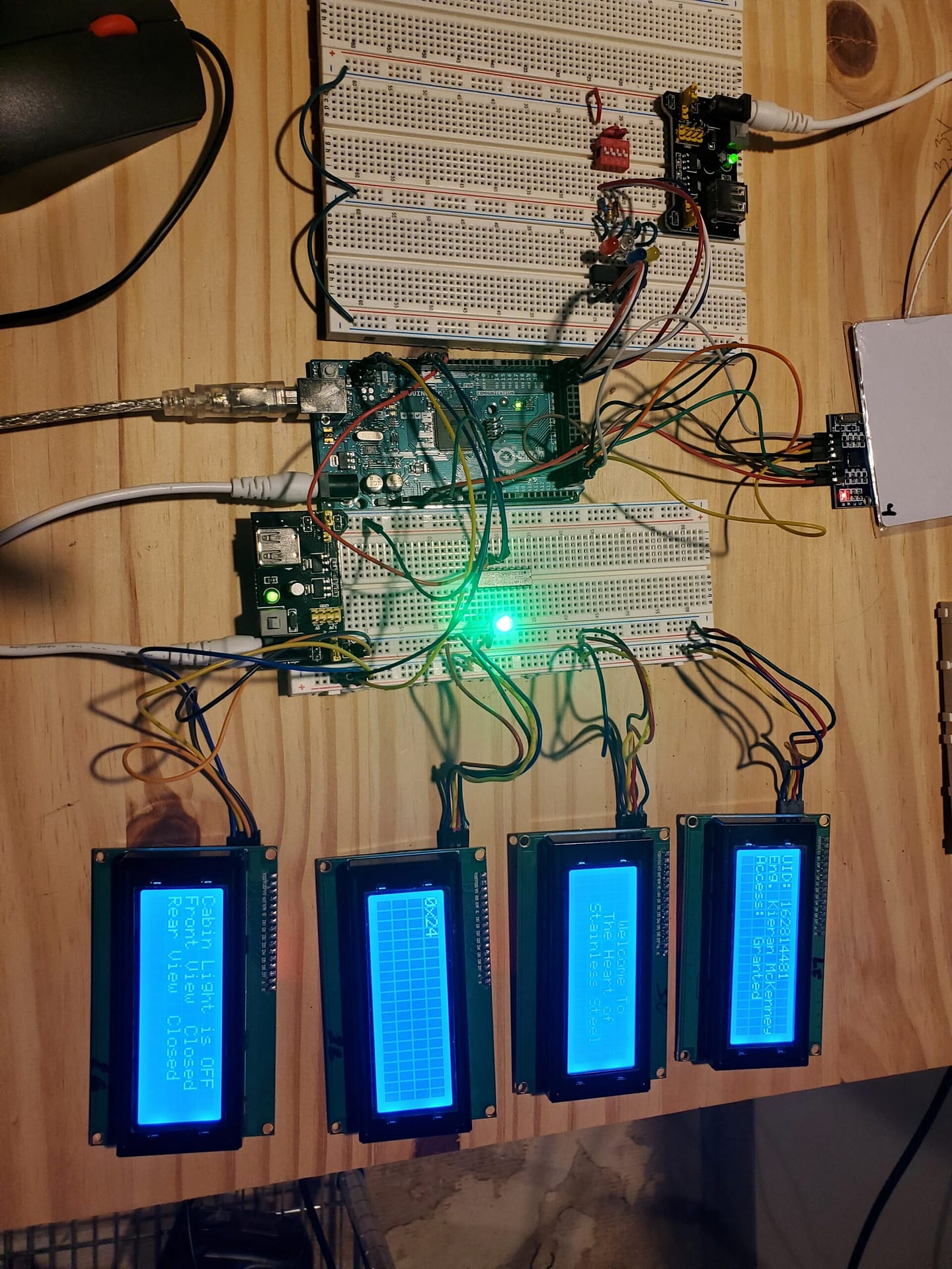
4 162814481 Eng. Kieran McKenney A2 51 2C 51 Granted
5 16711203167 Blank Blank Blank A7 0B CB A7 Denied
6
String crew[rows][columns] = { { "1", "1701796041", "Capt.", "Douglas", "Adams", "AA", "B3", "3C", "29", "Granted"},
{ "2", "23715925245", "Lt.", "Ford", "Prefect", "ED", "9F", "FC", "2D", "Granted" },
{ "3", "", "", "", "", "", "", "", "", "" },
{ "4", "162814481", "Eng.", "Kieran", "McKenney", "A2", "51", "2C", "51", "Granted" },
{ "5", "16711203167", "Blank", "Blank", "Blank", "A7", "0B", "CB", "A7", "Denied"},
{ "6", "", "", "", "", "", "", "", "", ""} };
*/
#include <SPI.h>
#include <MFRC522.h>
#include <Wire.h> // Library for I2C Wire
// C++ creates class objects. The class is LiquidCrystal_I2C. Each LCD has its own class based on its address.
#include <LiquidCrystal_I2C.h> // Library for I2C LCD displays
LiquidCrystal_I2C lcd_20(0x20, 20, 4); // I2C address 0x20, 20 column and 4 rows
LiquidCrystal_I2C lcd_21(0x21, 20, 4); // I2C address 0x21, 20 column and 4 rows
LiquidCrystal_I2C lcd_22(0x22, 20, 4); // I2C address 0x22, 20 column and 4 rows
LiquidCrystal_I2C lcd_23(0x23, 20, 4); // I2C address 0x23, 20 column and 4 rows
LiquidCrystal_I2C lcd_24(0x24, 20, 4); // I2C address 0x24, 20 column and 4 rows
LiquidCrystal_I2C lcd_25(0x25, 20, 4); // I2C address 0x25, 20 column and 4 rows
LiquidCrystal_I2C lcd_26(0x26, 20, 4); // I2C address 0x25, 20 column and 4 rows
LiquidCrystal_I2C lcd_27(0x27, 20, 4); // I2C address 0x25, 20 column and 4 rows
/* Typical pin layout used:
* -----------------------------------------------------------------------------------------
* MFRC522 Arduino Arduino Arduino Arduino Arduino
* Reader/PCD Uno/101 Mega Nano v3 Leonardo/Micro Pro Micro
* Signal Pin Pin Pin Pin Pin Pin
* -----------------------------------------------------------------------------------------
* RST/Reset RST 9 5 D9 RESET/ICSP-5 RST
* SPI SS SDA(SS) 10 53 D10 10 10
* SPI MOSI MOSI 11 / ICSP-4 51 D11 ICSP-4 16
* SPI MISO MISO 12 / ICSP-1 50 D12 ICSP-1 14
* SPI SCK SCK 13 / ICSP-3 52 D13 ICSP-3 15
*
*/
#define SSPin 53//define sda pin
#define RSTPin 5 //define reset pin
#
int redPin = 8; //pin connected to red cathode of RGB LED
int greenPin = 9; //pin connected to green cathode of RGB LED
int bluePin = 10; //pin connected to blue cathode of RGB LED
int IntRC[4]; // This converts the key fob ID to integers
int Dly = 1000;
String readCard[4]; //array for storing the UID of the card, 4 is the size because it will store 4 hexadecimal values but convert to string for easy identity checking later on
MFRC522 mfrc522(SSPin, RSTPin); //create instance of mfrc522 class
MFRC522::MIFARE_Key key; //create key structure used to store card info
//custom color writer func for rbg led
void RGBColorPicker(int redValue, int greenValue, int blueValue) { //3 parameters, red, green, blue value are used for writing the different color values to make a single color to display on the LED
analogWrite(redPin, redValue); //write specific value for red aspect of the RGB LED
analogWrite(greenPin, greenValue); //write specific value for green aspect of the RGB LED
analogWrite(bluePin, blueValue); //write specific value for blue aspect of the RGB LED
}
//reads card uid stores in string
String readCardUID(String UIDToRead) { //parameter: UIDToRead used to pass a string in which we want to store the UID
for (int i = 0; i < mfrc522.uid.size; i++){ // create a loop to go through the UID, for which the end of the reading is defined by the size
readCard[i] = String(mfrc522.uid.uidByte[i]); //mfrc522.uid.uidByte = an array containing the entire uid for our card but we can only take it out one byte at a time; convert to string so we can store it in our redCard array
IntRC[i] = readCard[i].toInt();
UIDToRead = UIDToRead + readCard[i]; //continuously concatanate the read byte into our passed string, UIDToRead
}
return(UIDToRead);
}
/*
//reveals secret message for user
void revealMessage(String secondReadUID){ //stores secondReadUID parameter in String form to eventually call readCard function with that parameter
while(true){ //create initial loop
if (mfrc522.PICC_IsNewCardPresent() && mfrc522.PICC_ReadCardSerial()){ //checks to see if card is available to read
if (readCardUID(secondReadUID) == "1701796041"){ //authorizing the UID
Serial.println("secret message"); //example secret message
break; //escape condition
}
else{ //if the read UID is not the one specified above:
Serial.println("Who are you?"); //print message
RGBColorPicker(255,0,0); //turn RGB LED on full red
break; //escape condition
}
}
}
}
*/
void setup() {
// Arduino Mega on I2C Bus
// I usually connect my Arduino devices and Raspberry Pi devices to the I2C bus. This will start the addresses at 0x50.
Wire.begin(0x50);
// I2C LCD screens are on addresses 0x20 to 0x27. This code is used to find all of the I2C LCDs attached.
lcd_20.clear(); // clear display 0x20
lcd_20.init(); // initialize the lcd
lcd_20.backlight();
lcd_20.setCursor(0, 0);
lcd_20.print("0x20");
lcd_21.clear(); // clear display 0x21
lcd_21.init(); // initialize the lcd
lcd_21.backlight();
lcd_21.setCursor(0, 0);
lcd_21.print("0x21");
lcd_22.clear(); // clear display 0x22
lcd_22.init(); // initialize the lcd
lcd_22.backlight();
lcd_22.setCursor(0, 0);
lcd_22.print("0x22");
lcd_23.clear(); // clear display 0x23
lcd_23.init(); // initialize the lcd
lcd_23.backlight();
lcd_23.setCursor(0, 0);
lcd_23.print("0x23");
lcd_24.clear(); // clear display 0x24
lcd_24.init(); // initialize the lcd
lcd_24.backlight();
lcd_24.setCursor(0, 0);
lcd_24.print("0x22");
lcd_25.clear(); // clear display 0x25
lcd_25.init(); // initialize the lcd
lcd_25.backlight();
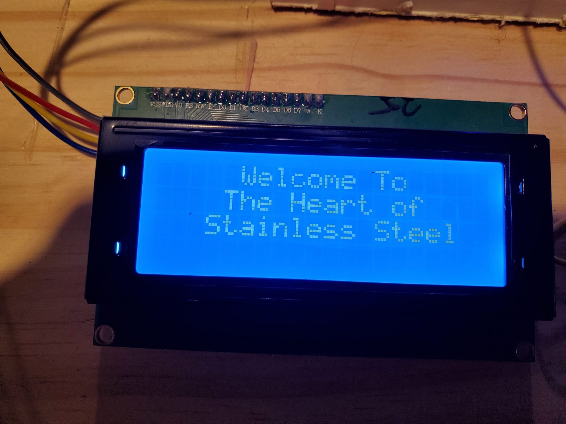
lcd_25.setCursor(5, 0); // move cursor to (5, 0)
lcd_25.print("Welcome To");
lcd_25.setCursor(4, 1); // move cursor to (4, 1)
lcd_25.print("The Heart of");
lcd_25.setCursor(3, 2); // move cursor to (3, 2)
lcd_25.print("Stainless Steel");
lcd_26.clear(); // clear display 0x26
lcd_26.init(); // initialize the lcd
lcd_26.backlight();
lcd_26.setCursor(0, 0);
lcd_26.print("0x26"); // print message at (0, 0)
// 0x27 is in use with the RFID tagging system.
lcd_27.clear(); // clear display 0x27
lcd_27.init(); // initialize the lcd 0x27
lcd_27.backlight();
//define RGB LED outputs
pinMode(redPin, OUTPUT);
pinMode(greenPin, OUTPUT);
pinMode(bluePin, OUTPUT);
RGBColorPicker(0,0,255); //initialize our RGB LED at color blue
SPI.begin(); //begin SPI bus
mfrc522.PCD_Init(); //initialize mfrc522 card
for (byte i = 0; i < 6; i++){
key.keyByte[i] = 0xFF; //set key security id values to 0xFF across the board
}
lcd_27.setCursor(0, 0); // move cursor to (0, 0)
lcd_27.print("Scan "); // print message at (0, 0)
}
void loop() {
// I usually use arrays for data groups. This group is the RFID information, rank and crew members.
int rows = 6;
int columns = 10;
String crew[rows][columns] = { { "1", "1701796041", "Capt.", "Douglas", "Adams", "AA", "B3", "3C", "29", "Granted"},
{ "2", "23715925245", "Lt.", "Ford", "Prefect", "ED", "9F", "FC", "2D", "Granted" },
{ "3", "", "", "", "", "", "", "", "", "" },
{ "4", "162814481", "Eng.", "Kieran", "McKenney", "A2", "51", "2C", "51", "Granted" },
{ "5", "16711203167", "", "", "", "A7", "0B", "CB", "A7", "Denied"},
{ "6", "", "", "", "", "", "", "", "", ""} };
String UID = ""; //first read
String SecondRead = ""; //second read
// if new card is not present rerun loop
if (!mfrc522.PICC_IsNewCardPresent()){
return;
}
//select card to read
if (!mfrc522.PICC_ReadCardSerial()){
return;
}
UID = readCardUID(UID); //call the readCardUID function and store it in UID variable
for ( int i = 0; i <= 6; i++ ) {
RGBColorPicker(0,0,255); //Start RGB LED as Blue
if ( UID == crew[i][1]){
//print to I2C LCD 0x27 UID on line 1
lcd_27.clear(); // clear display
lcd_27.setCursor(0, 0); // move cursor to (0, 0)
lcd_27.print("UID: "); // print message at (0, 0)
lcd_27.setCursor(5, 0); // move cursor to (5.0)
lcd_27.print(UID); // print message at (2, 1)
lcd_27.setCursor(0, 1); // move cursor to (0, 1)
lcd_27.print(crew[i][2]); // print message at (0, 1)
lcd_27.print(" ");
lcd_27.print(crew[i][3]); // print message at (0, 1)
lcd_27.print(" ");
lcd_27.print(crew[i][4]);
lcd_27.setCursor(0, 2); // move cursor to (0, 2)
lcd_27.print("Access: ");
lcd_27.setCursor(9, 2); // move cursor to (9, 2)
lcd_27.print(crew[i][9]);
// print message at (0, 1)
if (crew[i][9] == "Granted")
{
// RGBColorPicker(0,255,0); //set color to green
RGBColorPicker(0,255,0);
delay(Dly);
}
else if (crew[i][9] == "Denied")
{
// RGBColorPicker(0,255,0); //set color to red
RGBColorPicker(255,0,0);
delay(Dly);
}
}
lcd_27.clear(); // clear display
//Serial.println("Scan card for message: "); //scan card for secret message
//delay(500);
//revealMessage(SecondRead); //calls revealMessage function, storing the second read of the UID into variable SecondRead
} //end of for loop
mfrc522.PICC_HaltA(); //stops reading
lcd_27.setCursor(0, 0); // move cursor to (0, 0)
lcd_27.print("Scan: "); //end of loop -> prompts user to scan again
RGBColorPicker(0,0,255);
}
Captain Douglas Adams, 2 Officers, and his Engineer have access to the command center. The RGB LED will be green for access granted and red for access denied. It turns blue for scan…
I used the dumpinfo.ino in mfrc522 folder to get the HEX addresses for each of the key fobs and key cards. The program converts them to the integer strings. The text file above is up to date.
array for crew
1 1701796041 Capt. Douglas Adams AA B3 3C 29 Granted
2 23715925245 Lt. Ford Prefect ED 9F FC 2D  Granted
3 //Returned with damaged RFID
4 162814481 Eng. Kieran McKenney A2 51 2C 51 Denied
5 16711203167 Blank Blank Blank A7 0B CB A7  Denied
6 //Returned with damaged RFID

String crew[rows][columns] = { { "1", "1701796041", "Capt.", "Douglas", "Adams", "AA", "B3", "3C", "29", "Granted"},
{ "2", "23715925245", "Lt.", "Ford", "Prefect", "ED", "9F", "FC", "2D", "Granted" },
{ "3", "", "", "", "", "", "", "", "" , ""},
{ "4", "162814481", "Eng.", "Kieran", "McKenney", "A2", "51", "2C", "51", "Granted" },
{ "5", "16711203167", "Blank", "Blank", "Blank", "A7", "0B", "CB", "A7", "Denied"},
{ "6", "", "", "", "", "", "", "", "", ""} };