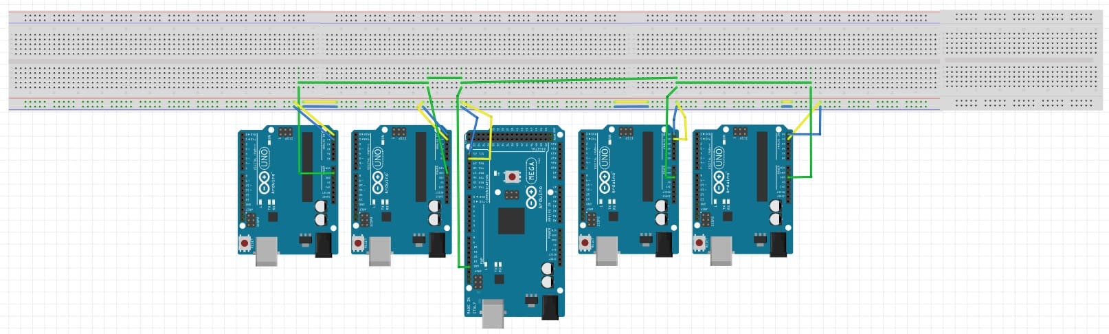
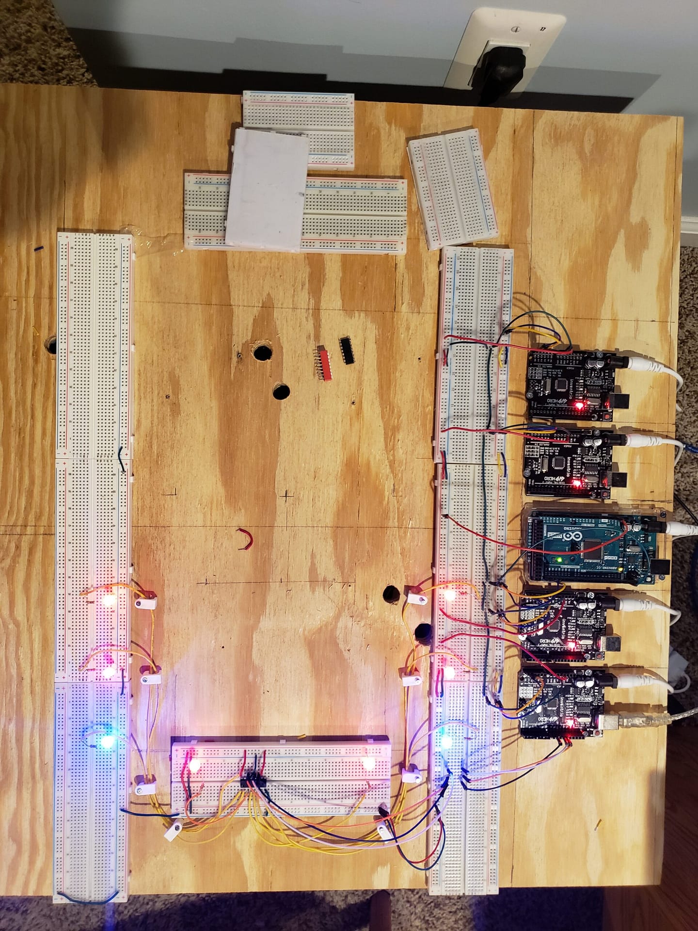
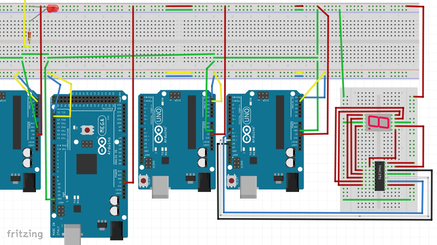
My ship has limited power. So I am creating three bus paths: Ground, 5V, and 3.3V. It will also help with the limited amount of wire I have. It is important to not have ground loops. Ground loop is an unwanted electric current path in a circuit resulting in stray signals or interference, occurring, e.g., when two earthed points in the same circuit have different potentials. The 9V-1A power supplies share the same ground. If you follow each ground path, they end without connecting back. I made sure both sides of each bread board are grounded
Green: Ground
Red: 5V
White: 3.3V
I will keep 5V and 3.3V isolated on the control boards. Still need to connect up the 3.3V. I will also not to create loops. Ground loops are very bad.
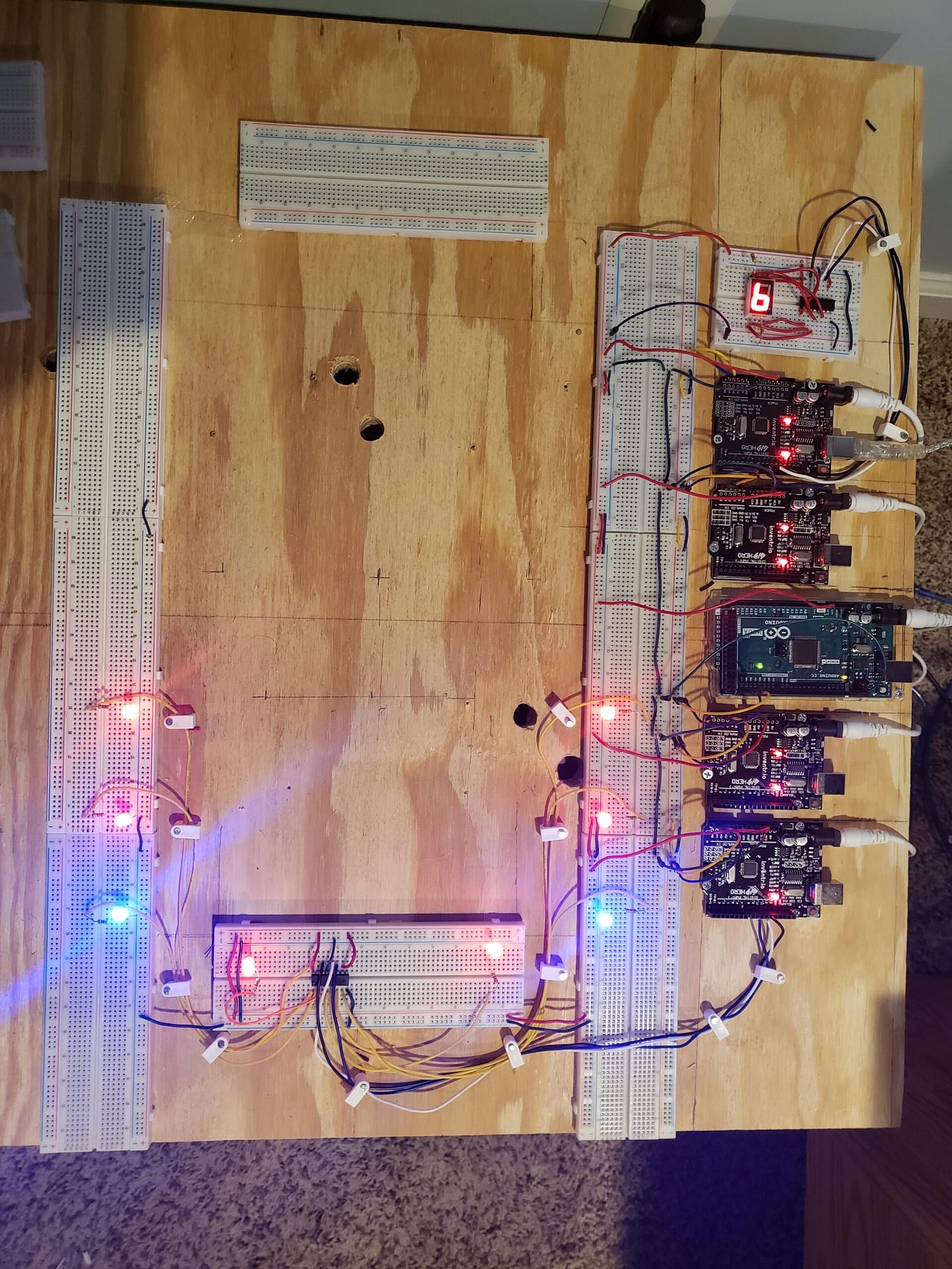
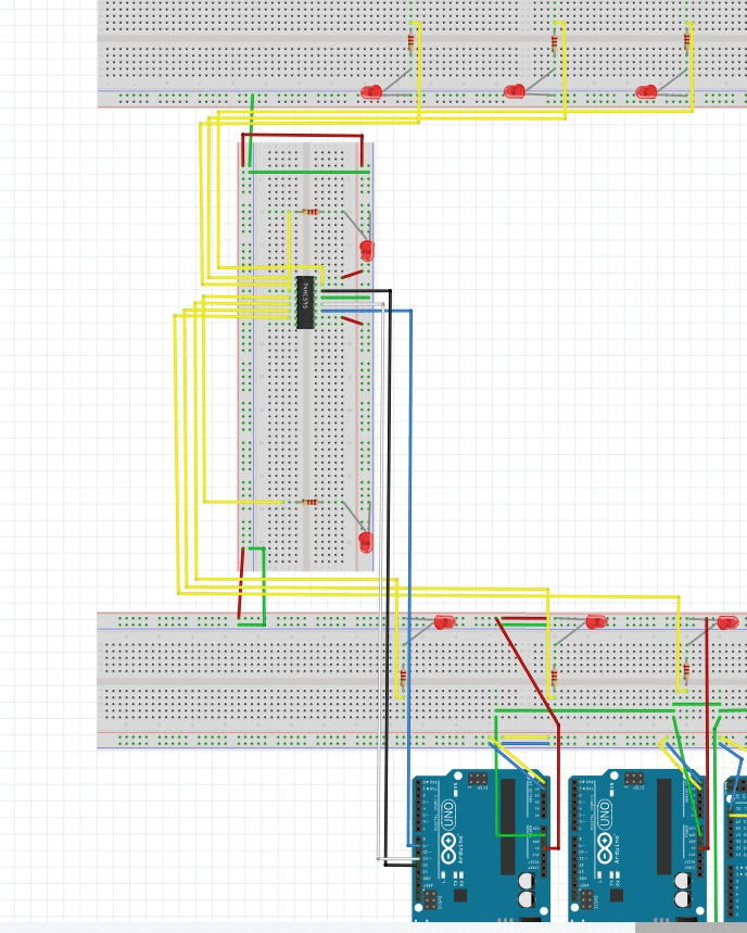
I was able to find a few SN74HC595N shift registers to connect the lighting up with. This saves on wire and ports of the controllers. I added 8 position dip switches and SIPO and PISO shift registers to this project.

Code
Master
// Include the required Wire library for I2C

#include <Wire.h>
int x = 0;
int LED = 13;

void setup(){
pinMode (LED, OUTPUT);
// Start the I2C Bus as Master
Wire.begin();
}

void loop() {
x++; // Increment x
//From Left to Right
// First UNO
Wire.beginTransmission(1); // transmit to device #1
Wire.write(x); // sends x
Wire.endTransmission(); // stop transmitting

//Second UNO
Wire.beginTransmission(2); // transmit to device #2
Wire.write(x); // sends x
Wire.endTransmission(); // stop transmitting

//Mega in the Middle

//Third UNO
Wire.beginTransmission(3); // transmit to device #3
Wire.write(x); // sends x
Wire.endTransmission(); // stop transmitting

//Fourth UNO
Wire.beginTransmission(4); // transmit to device #4
Wire.write(x); // sends x
Wire.endTransmission(); // stop transmitting

if ( (x == 3) || (x == 6)) {
digitalWrite(LED, HIGH);
}
else {
digitalWrite(LED, LOW);
}

if (x == 7) x = 0; // `reset x once it gets 6
delay(1000);

}
Slave 1
#include <Wire.h>
int LED = 13;
int latchPin=11;
int clockPin=9;
int dataPin=12;
int x = 0;
int dt=250;

byte LEDsOff=0b00000000;
byte LEDsOn=0b11111111;
byte LEDs1=0b10000000;
byte LEDs2=0b01000000;
byte LEDs3=0b00100000;
byte LEDs4=0b00010000;
byte LEDs5=0b00001000;
byte LEDs6=0b00000100;
byte LEDs7=0b00000010;
byte LEDs8=0b00000001;

void setup() {
Serial.begin(9600);
pinMode (LED, OUTPUT);
pinMode (latchPin,OUTPUT);
pinMode (dataPin,OUTPUT);
pinMode (clockPin,OUTPUT);

//SN74HC252

// Start the I2C Bus as Slave on address 1
Wire.begin(1);
// Attach a function to trigger when something is received.
Wire.onReceive(receiveEvent);
}
void receiveEvent(int bytes) {
x = Wire.read(); // read one character from the I2C
}

void loop() {
if (x == 1) {
digitalWrite(LED, HIGH);
}
else {
digitalWrite(LED, LOW);
}

if (x == 6) {
digitalWrite(LED, HIGH);
delay(500);
digitalWrite(LED, LOW);
}

//SN74HC252 Loop 1 to 8

digitalWrite(latchPin,LOW);
shiftOut(dataPin,clockPin,LSBFIRST,LEDsOn);
digitalWrite(latchPin,HIGH);
delay(dt);

/*
digitalWrite(latchPin,LOW);
shiftOut(dataPin,clockPin,LSBFIRST,LEDsOff);
digitalWrite(latchPin,HIGH);
delay(dt);

digitalWrite(latchPin,LOW);
shiftOut(dataPin,clockPin,LSBFIRST,LEDs1);
digitalWrite(latchPin,HIGH);
delay(dt);

digitalWrite(latchPin,LOW);
shiftOut(dataPin,clockPin,LSBFIRST,LEDs2);
digitalWrite(latchPin,HIGH);
delay(dt);

digitalWrite(latchPin,LOW);
shiftOut(dataPin,clockPin,LSBFIRST,LEDs3);
digitalWrite(latchPin,HIGH);
delay(dt);

digitalWrite(latchPin,LOW);
shiftOut(dataPin,clockPin,LSBFIRST,LEDs4);
digitalWrite(latchPin,HIGH);
delay(dt);

digitalWrite(latchPin,LOW);
shiftOut(dataPin,clockPin,LSBFIRST,LEDs5);
digitalWrite(latchPin,HIGH);
delay(dt);

digitalWrite(latchPin,LOW);
shiftOut(dataPin,clockPin,LSBFIRST,LEDs6);-
digitalWrite(latchPin,HIGH);
delay(dt);

digitalWrite(latchPin,LOW);
shiftOut(dataPin,clockPin,LSBFIRST,LEDs7);
digitalWrite(latchPin,HIGH);
delay(dt);

digitalWrite(latchPin,LOW);
shiftOut(dataPin,clockPin,LSBFIRST,LEDs8);
digitalWrite(latchPin,HIGH);
delay(dt);
*/

}
Slave 2
#include <Wire.h>
int LED = 13;
int x = 0;
void setup() {
pinMode (LED, OUTPUT);
// Start the I2C Bus as Slave on address 2
Wire.begin(2);
// Attach a function to trigger when something is received.
Wire.onReceive(receiveEvent);
}
void receiveEvent(int bytes) {
x = Wire.read(); // read one character from the I2C
}

void loop() {
if (x == 2) {
digitalWrite(LED, HIGH);
}
else {
digitalWrite(LED, LOW);
}

if (x == 6) {
digitalWrite(LED, HIGH);
delay(500);
digitalWrite(LED, LOW);
}

}
Slave 3
#include <Wire.h>
int LED = 13;
int x = 0;
void setup() {
pinMode (LED, OUTPUT);
// Start the I2C Bus as Slave on address 3
Wire.begin(3);
// Attach a function to trigger when something is received.
Wire.onReceive(receiveEvent);
}
void receiveEvent(int bytes) {
x = Wire.read(); // read one character from the I2C
}

void loop() {
if (x == 4) {
digitalWrite(LED, HIGH);
}
else {
digitalWrite(LED, LOW);
}

if (x == 6) {
digitalWrite(LED, HIGH);
delay(500);
digitalWrite(LED, LOW);
}

}
Slave 4
#include <Wire.h>
int LED = 13;
int latchPin=11;
int clockPin=9;
int dataPin=12;
int x = 0;
int dt=250;

byte LEDsOff=0b00000000;
byte LEDsOn=0b11111111;
byte LEDs1=0b10000000;
byte LEDs2=0b01000000;
byte LEDs3=0b00100000;
byte LEDs4=0b00010000;
byte LEDs5=0b00001000;
byte LEDs6=0b00000100;
byte LEDs7=0b00000010;
byte LEDs8=0b00000001;

byte LEDZero = 0b11111100;
byte LEDOne = 0b01100000;
byte LEDTwo = 0b11011010;
byte LEDThree = 0b11110010;
byte LEDFour = 0b01100110;
byte LEDFive = 0b10110110;
byte LEDSix = 0b00111110;

void setup() {
pinMode (LED, OUTPUT);
pinMode (latchPin,OUTPUT);
pinMode (dataPin,OUTPUT);
pinMode (clockPin,OUTPUT);

// Start the I2C Bus as Slave on address 4
Wire.begin(4);
// Attach a function to trigger when something is received.
Wire.onReceive(receiveEvent);
}
void receiveEvent(int bytes) {
x = Wire.read(); // read one character from the I2C
}

void loop() {
/*
// test all LED display
digitalWrite(latchPin,LOW);
shiftOut(dataPin,clockPin,LSBFIRST,LEDsOn);
digitalWrite(latchPin,HIGH);
delay(dt);
*/

if (x == 1) {
digitalWrite(latchPin,LOW);
shiftOut(dataPin,clockPin,LSBFIRST,LEDOne);
digitalWrite(latchPin,HIGH);
}

if (x == 2) {
digitalWrite(latchPin,LOW);
shiftOut(dataPin,clockPin,LSBFIRST,LEDTwo);
digitalWrite(latchPin,HIGH);
}

if (x == 3) {
digitalWrite(latchPin,LOW);
shiftOut(dataPin,clockPin,LSBFIRST,LEDThree);
digitalWrite(latchPin,HIGH);
}

if (x == 4) {
digitalWrite(latchPin,LOW);
shiftOut(dataPin,clockPin,LSBFIRST,LEDFour);
digitalWrite(latchPin,HIGH);
}

if (x == 5) {
digitalWrite(LED, HIGH);
//LED display
digitalWrite(latchPin,LOW);
shiftOut(dataPin,clockPin,LSBFIRST,LEDFive);
digitalWrite(latchPin,HIGH);
}
else {
digitalWrite(LED, LOW);
}

if (x == 6) {
digitalWrite(LED, HIGH);

//LED display
digitalWrite(latchPin,LOW);
shiftOut(dataPin,clockPin,LSBFIRST,LEDSix);
digitalWrite(latchPin,HIGH);

//On Board LED
digitalWrite(LED, LOW);
}

//SN74HC252 Loop 1 to 8
/*
digitalWrite(latchPin,LOW);
shiftOut(dataPin,clockPin,LSBFIRST,LEDsOn);
digitalWrite(latchPin,HIGH);
delay(dt);

digitalWrite(latchPin,LOW);
shiftOut(dataPin,clockPin,LSBFIRST,LEDsOff);
digitalWrite(latchPin,HIGH);
delay(dt);

digitalWrite(latchPin,LOW);
shiftOut(dataPin,clockPin,LSBFIRST,LEDs1);
digitalWrite(latchPin,HIGH);
delay(dt);

digitalWrite(latchPin,LOW);
shiftOut(dataPin,clockPin,LSBFIRST,LEDs2);
digitalWrite(latchPin,HIGH);
delay(dt);

digitalWrite(latchPin,LOW);
shiftOut(dataPin,clockPin,LSBFIRST,LEDs3);
digitalWrite(latchPin,HIGH);
delay(dt);

digitalWrite(latchPin,LOW);
shiftOut(dataPin,clockPin,LSBFIRST,LEDs4);
digitalWrite(latchPin,HIGH);
delay(dt);

digitalWrite(latchPin,LOW);
shiftOut(dataPin,clockPin,LSBFIRST,LEDs5);
digitalWrite(latchPin,HIGH);
delay(dt);

digitalWrite(latchPin,LOW);
shiftOut(dataPin,clockPin,LSBFIRST,LEDs6);-
digitalWrite(latchPin,HIGH);
delay(dt);

digitalWrite(latchPin,LOW);
shiftOut(dataPin,clockPin,LSBFIRST,LEDs7);
digitalWrite(latchPin,HIGH);
delay(dt);

digitalWrite(latchPin,LOW);
shiftOut(dataPin,clockPin,LSBFIRST,LEDs8);
digitalWrite(latchPin,HIGH);
delay(dt);
*/

}