Stardate 98788.27
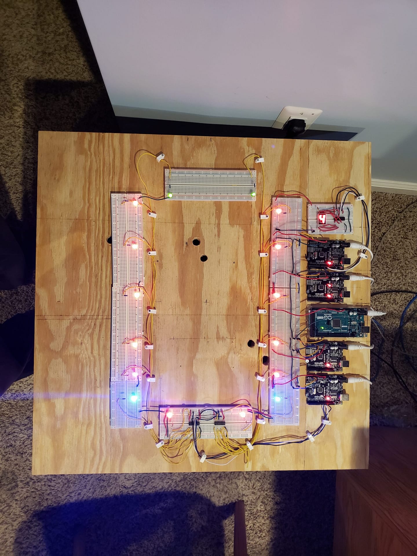
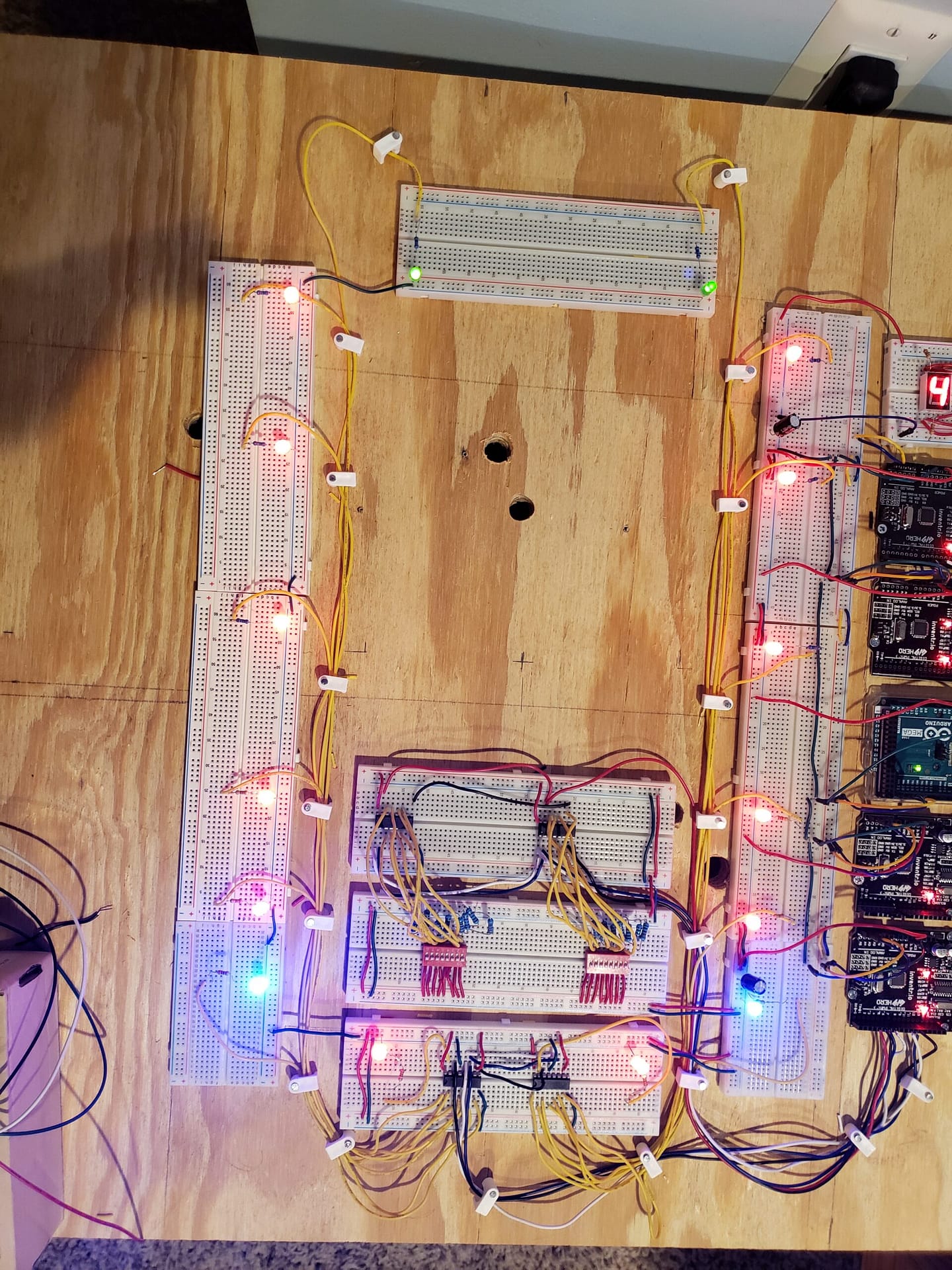
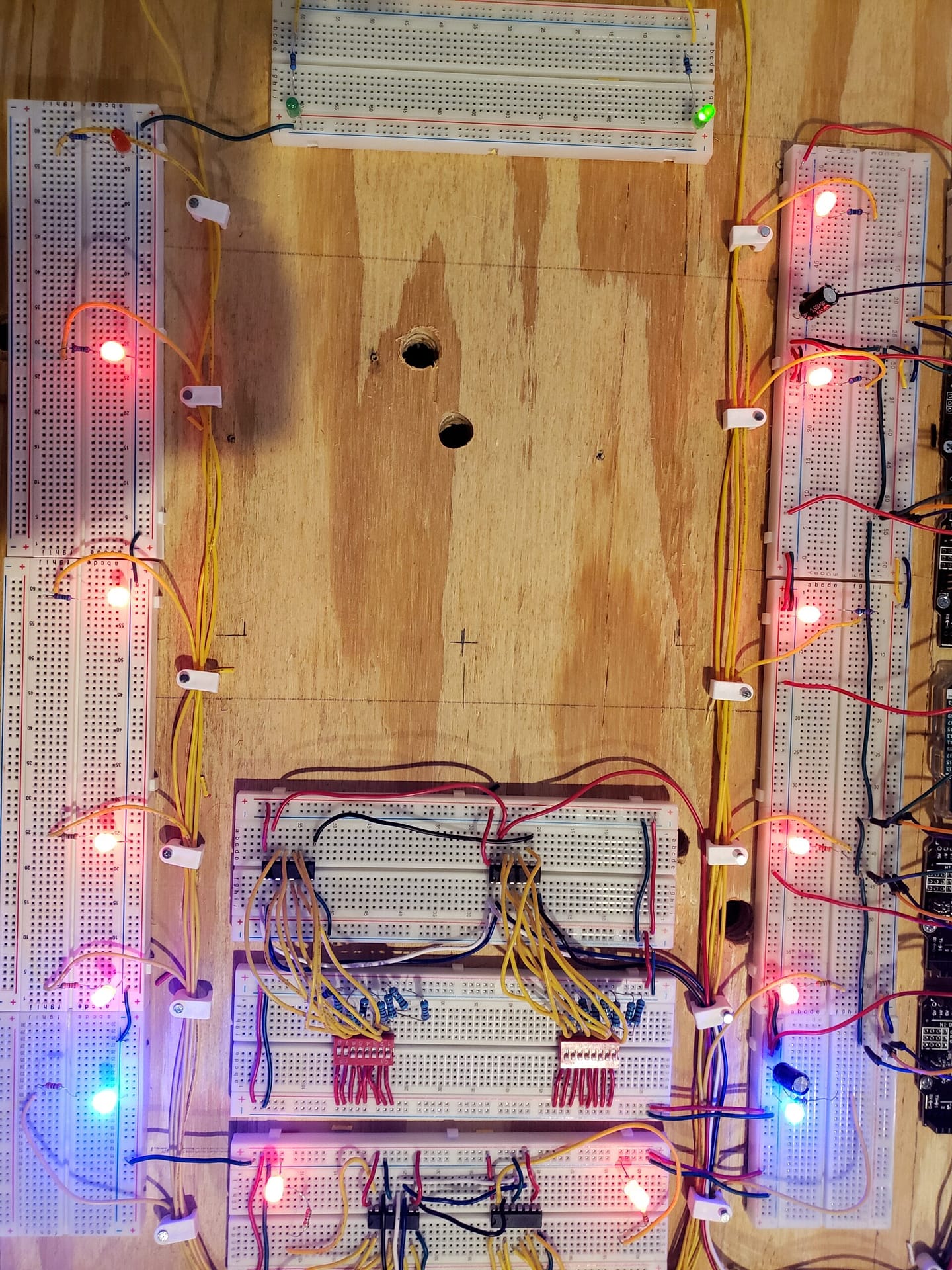
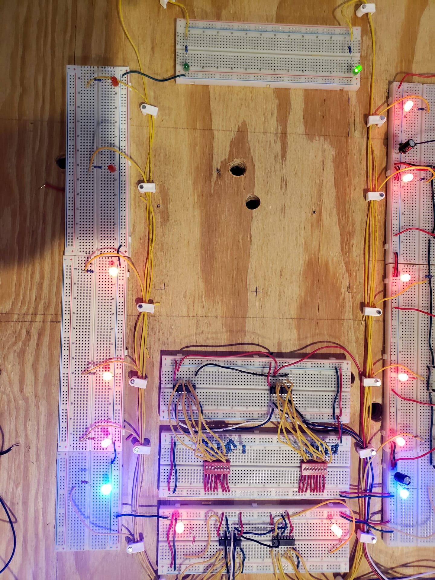
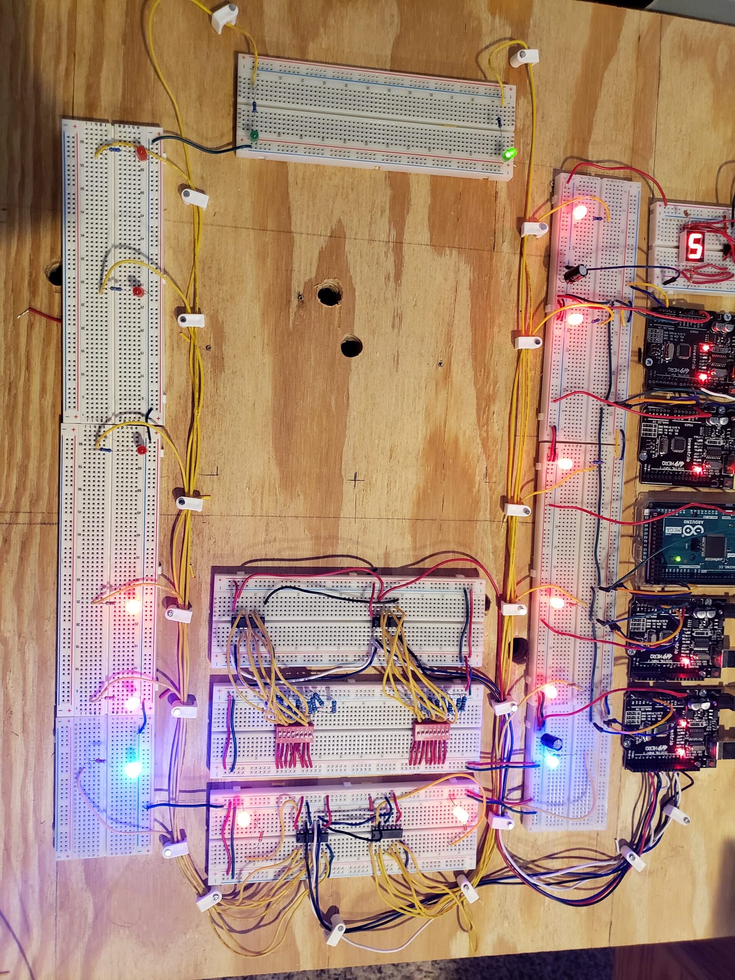
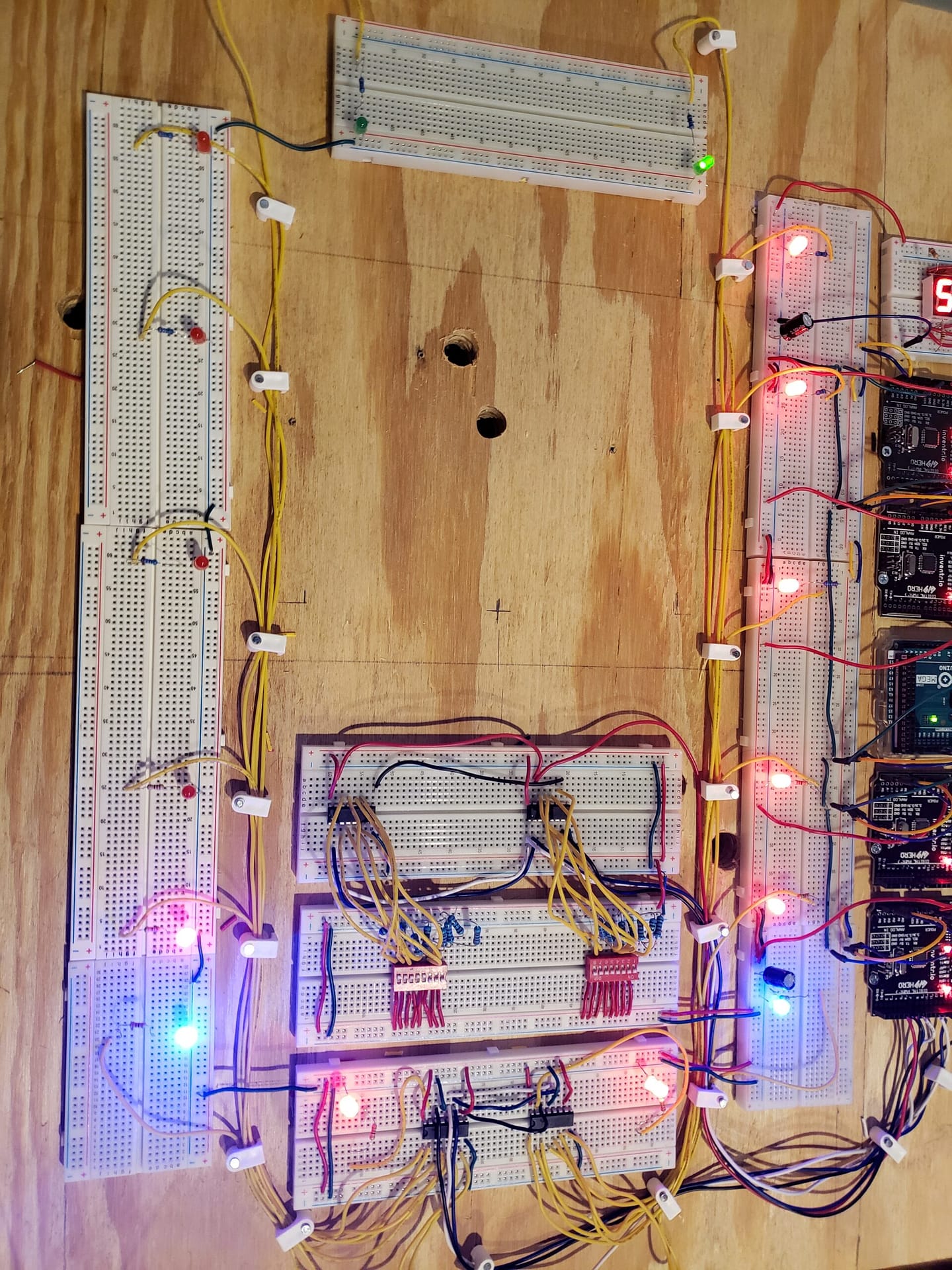
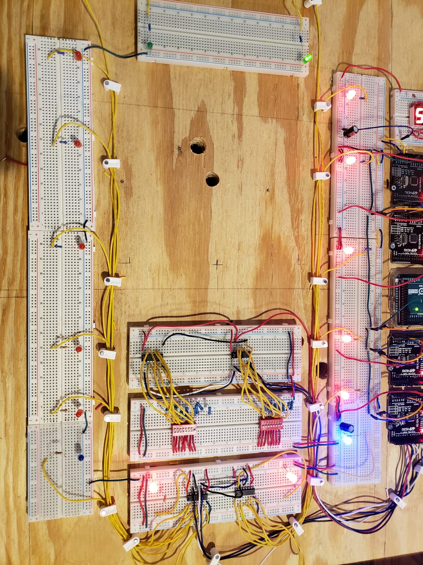
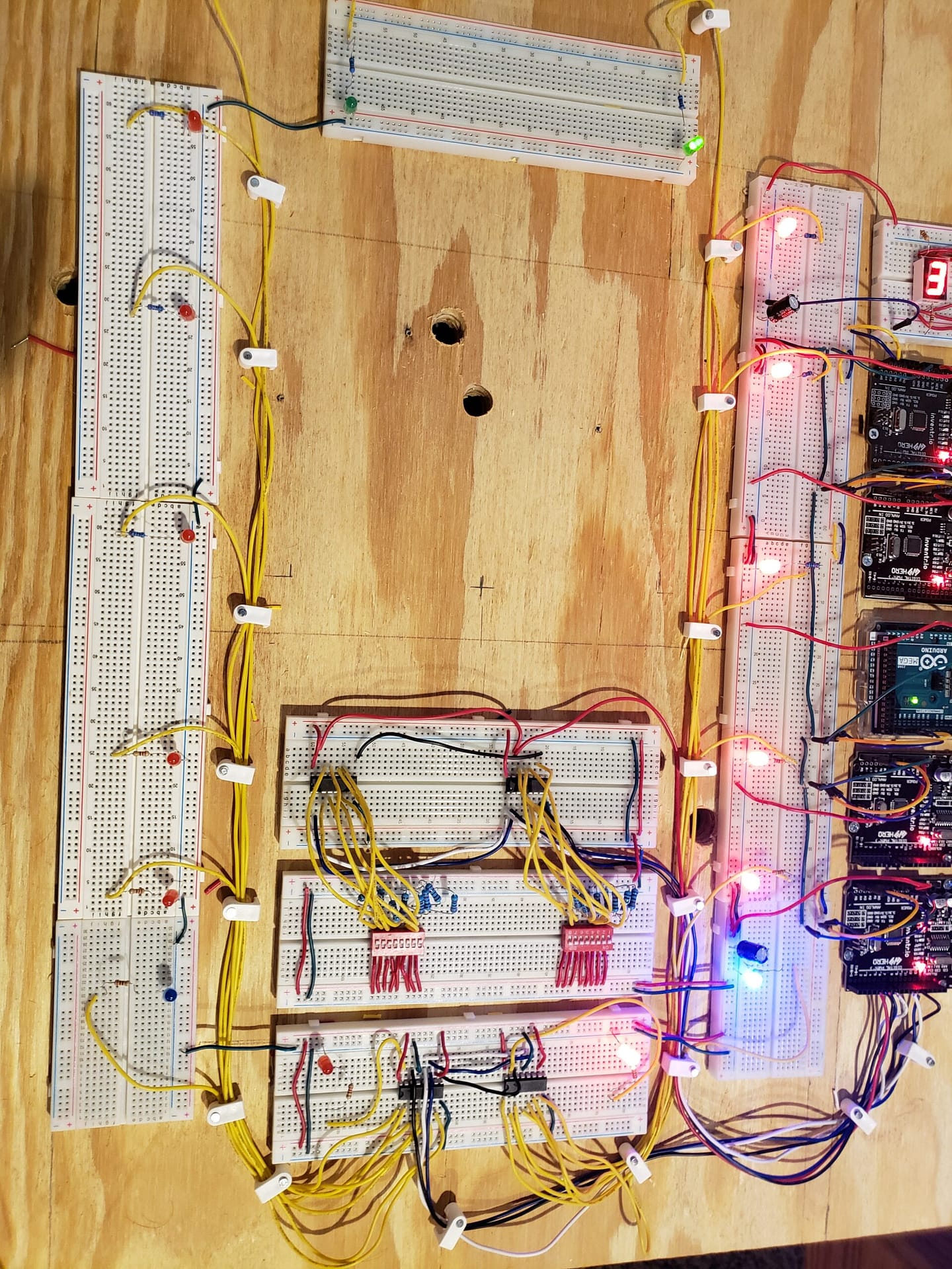
Day 5 trapped in my broken spaceship. I managed to cascade two SN74HC595 SIPO modules together to get 16 lights working front to back. The I2C computer is functioning.
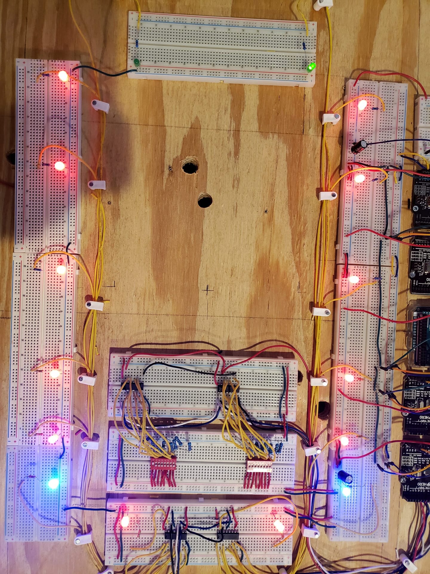
I placed two 100μf capacitors on the 5V power bus just outside the 5V connections of slave 1 and 4 to clean up the DC power.
7 connections to Slave 1 for SN74HC165 and SN74HC595. 16 dip switches going to 16 LEDs. So 7 connections controls 32 things.
The two SN74HC595N SIPO Shift Registers are cascaded together.
Master – Slave HC74HC595N
Pin 9 to pin 13: Black
Pin 11 to pin 11: Blue:
Pin 12 to pin 12: White
Grounds and 5V are on the same buses.
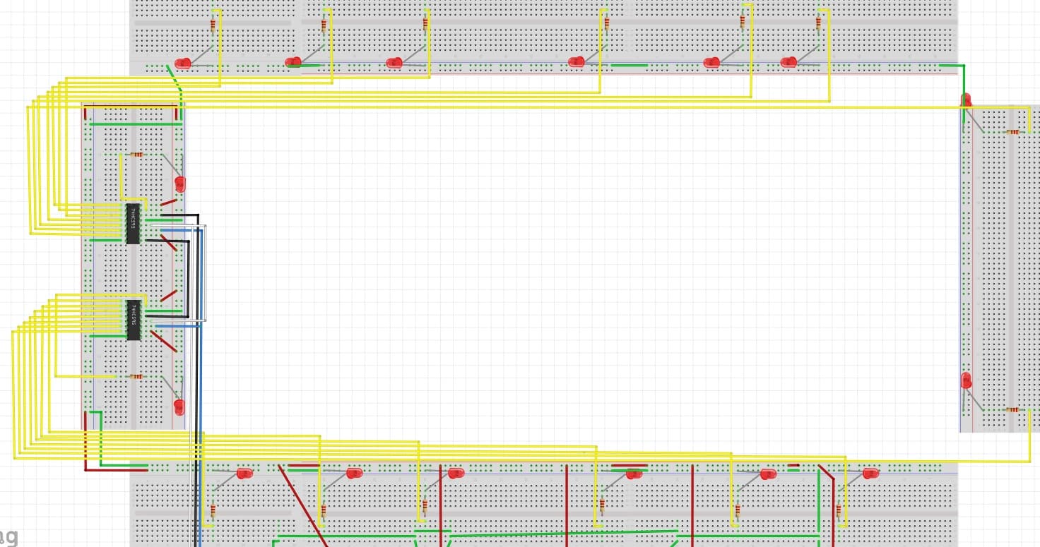
I found in the back of the ship some 8 dip switches and SN74HC165 PISO shift registers. In order to save power in the ship, I connected each LED to a dip switch.
Dip switch 1 : front Red LED
Dip switch 2: front Blue LED
Dip switch 8: back Green LED
SN74HC165
A : switch 8
B: switch 7
C: switch 6
D: switch 5
E: switch 4
F: switch 3
G: switch 2
H: switch 1
Both of the SN74HC595 and SN74HC165 are cascaded so it was a 16 bit Byte.
SH74HC165 to Arduino
Pin 1 to Pin 7
Pin 2 to Pin 6
Pin 7 to Pin 5
Pin 15 to Pin 4
Master Arduino to Slave Arduino
Pin 10 to Pin 9
SN74HC165
A : switch 8
B: switch 7
C: switch 6
D: switch 5
E: switch 4
F: switch 3
G: switch 2
H: switch 1
switch

Master
// Include the required Wire library for I2C
// Include the libraries:
// LiquidCrystal_I2C.h: https://github.com/johnrickman/LiquidCrystal_I2C
#include <Wire.h> // Library for I2C communication
#include <LiquidCrystal_I2C.h> // Library for LCD

// Wiring: SDA pin is connected to A4 and SCL pin to A5.
// Connect to LCD via I2C, default address 0x27 (A0-A2 not jumpered)
LiquidCrystal_I2C lcd16x2_23 = LiquidCrystal_I2C(0x23, 16, 2); // Change to (0x23,16,2) for 16x2 LCD.
LiquidCrystal_I2C lcd20x4_27 = LiquidCrystal_I2C(0x27, 20, 4); // Change to (0x27,20,4) for 20x4 LCD.


int x = 0;
int LED = 13;

void HeartOfStainlessSteel_20x4_27() {
lcd20x4_27.init();
lcd20x4_27.backlight();

lcd20x4_27.setCursor(3, 0); // 4th column 1st row
lcd20x4_27.print("Welcome aboard");

lcd20x4_27.setCursor(8, 1); // 9th column 2nd row
lcd20x4_27.print("the");

lcd20x4_27.setCursor(6, 2); // 7th column 3rd row
lcd20x4_27.print("Heart of");

lcd20x4_27.setCursor(2, 3); // 3rd column 4th row
lcd20x4_27.print("Stainless Steel");
}

void LCD16x2_23() {
lcd16x2_23.init();
lcd16x2_23.backlight();

//LCD I2C 160X2_23
lcd16x2_23.setCursor(3, 0); // 4th column 1st row
lcd16x2_23.print("I am 0x23");
//LCD I2C 160X2_23
}

void I2C_Begin() {
// I2C Scanner Code
Serial.begin(9600);
while (!Serial); // wait for serial monitor
Serial.println("\nI2C Scanner");
// I2C Scanner Code
}

void I2C_Find_Address() {
// I2C Scanner Code
byte error, address;
int nDevices;

Serial.println("Scanning...");

nDevices = 0;
for(address = 1; address < 127; address++ )
{
// The i2c_scanner uses the return value of
// the Write.endTransmisstion to see if
// a device did acknowledge to the address.
Wire.beginTransmission(address);
error = Wire.endTransmission();

if (error == 0)
{
Serial.print("I2C device found at address 0x");
if (address<16)
Serial.print("0");
Serial.print(address,HEX);
Serial.println(" !");

nDevices++;
}
else if (error==4)
{
Serial.print("Unknown error at address 0x");
if (address<16)
Serial.print("0");
Serial.println(address,HEX);
}
}
if (nDevices == 0)
Serial.println("No I2C devices found\n");
else
Serial.println("done\n");

delay(5000); // wait 5 seconds for next scan
// I2C Scanner Code
}

void setup() {

// comment out to stop the I2C find address
//I2C_Begin();
// comment out to stop the I2C find address

// These control the LCD displays
LCD16x2_23();
HeartOfStainlessSteel_20x4_27();

// I2C counter for LEDs
pinMode (LED, OUTPUT);
// Start the I2C Bus as Master
Wire.begin();
// I2C counter for LEDs
}

void loop() {

// comment out to stop the I2C find address
// I2C_Find_Address();
// comment out to stop the I2C find address

// I2C counter for LEDs
x++; // Increment x

//From Left to Right
// First UNO
Wire.beginTransmission(1); // transmit to device #1
Wire.write(x); // sends x
Wire.endTransmission(); // stop transmitting

//Second UNO
Wire.beginTransmission(2); // transmit to device #2
Wire.write(x); // sends x
Wire.endTransmission(); // stop transmitting

//Mega in the Middle

//Third UNO
Wire.beginTransmission(3); // transmit to device #3
Wire.write(x); // sends x
Wire.endTransmission(); // stop transmitting

//Fourth UNO
Wire.beginTransmission(4); // transmit to device #4
Wire.write(x); // sends x
Wire.endTransmission(); // stop transmitting

if ( (x == 3) || (x == 6)) {
digitalWrite(LED, HIGH);
}
else {
digitalWrite(LED, LOW);
}

if (x == 7) x = 0; // `reset x once it gets 6
delay(1000);
// I2C counter for LEDs

}
Slave 1
#include <Wire.h>

/*
* SN74HC165N_shift_reg
*
* Program to shift in the bit values from a SN74HC165N 8-bit
* parallel-in/serial-out shift register.
*
* This sketch demonstrates reading in 16 digital states from a
* pair of daisy-chained SN74HC165N shift registers while using
* only 4 digital pins on the Arduino.
*
* You can daisy-chain these chips by connecting the serial-out
* (Q7 pin) on one shift register to the serial-in (Ds pin) of
* the other.
*
* Of course you can daisy chain as many as you like while still
* using only 4 Arduino pins (though you would have to process
* them 4 at a time into separate unsigned long variables).
*
*/

uint8_t bytes_right;
uint8_t bytes_left;
uint8_t hex_left;
uint8_t hex_right;
/* How many shift register chips are daisy-chained.
*/
#define NUMBER_OF_SHIFT_CHIPS 2

/* Width of data (how many ext lines).
*/
#define DATA_WIDTH NUMBER_OF_SHIFT_CHIPS * 8

/* Width of pulse to trigger the shift register to read and latch.
*/
#define PULSE_WIDTH_USEC 5

/* Optional delay between shift register reads.
*/
#define POLL_DELAY_MSEC 1

/* You will need to change the "int" to "long" If the
* NUMBER_OF_SHIFT_CHIPS is higher than 2.
*/
#define BYTES_VAL_T unsigned int

//SN74HC595
int LED = 13;
int num = 0;
int Slave1_PR[1][2];

// ST_CP pin 12
int latchPin=10; // white
// SH_CP pin 11
int clockIn=11; // blue
// DS pin 14
int dataIn=12; // black

//I2C
int x = 0;
int dt=250;

//SN74HC165
int ploadPin = 7; // Connects to Parallel load pin the 165
int clockEnablePin = 4; // Connects to Clock Enable pin the 165
int dataPin = 5; // Connects to the Q7 pin the 165
int clockPin = 6; // Connects to the Clock pin the 165

byte dataArrayLeft;
byte dataArrayRight;

BYTES_VAL_T pinValues;
BYTES_VAL_T oldPinValues;

/* This function is essentially a "shift-in" routine reading the
* serial Data from the shift register chips and representing
* the state of those pins in an unsigned integer (or long).
*/
BYTES_VAL_T read_shift_regs()
{
long bitVal;
BYTES_VAL_T bytesVal = 0;

/* Trigger a parallel Load to latch the state of the data lines,
*/
digitalWrite(clockEnablePin, HIGH);
digitalWrite(ploadPin, LOW);
delayMicroseconds(PULSE_WIDTH_USEC);
digitalWrite(ploadPin, HIGH);
digitalWrite(clockEnablePin, LOW);

/* Loop to read each bit value from the serial out line
* of the SN74HC165N.
*/
for(int i = 0; i < DATA_WIDTH; i++)
{
bitVal = digitalRead(dataPin);

/* Set the corresponding bit in bytesVal.
*/
bytesVal |= (bitVal << ((DATA_WIDTH-1) - i));

/* Pulse the Clock (rising edge shifts the next bit).
*/
digitalWrite(clockPin, HIGH);
delayMicroseconds(PULSE_WIDTH_USEC);
digitalWrite(clockPin, LOW);
}

return(bytesVal);
}

/* Dump the list of zones along with their current status.
*/
void display_pin_values()
{
//Serial.print("PinValues:\r\n");
//Serial.print(pinValues, HEX);
//Serial.print("\r\n");

//Serial.print("\nInvert PinValues:\r\n");
//Serial.print(~pinValues, HEX);
//Serial.print("\r\n");
}

void setup()
{
Serial.begin(9600);

pinMode (LED, OUTPUT);
// Start the I2C Bus as Slave on address 2
Wire.begin(1);
// Attach a function to trigger when something is received.
Wire.onReceive(receiveEvent);

// Serial.begin(9600);

/* Initialize our digital pins...
*/
// 74HC165 pins
pinMode(ploadPin, OUTPUT);
pinMode(clockEnablePin, OUTPUT);
pinMode(clockPin, OUTPUT);
pinMode(dataPin, INPUT);

// 74HC595 pins
pinMode(latchPin,OUTPUT);
pinMode(dataIn,OUTPUT);
pinMode(clockIn,OUTPUT);

digitalWrite(latchPin, LOW);
digitalWrite(clockPin, LOW);
digitalWrite(ploadPin, HIGH);

/* Read in and display the pin states at startup.
*/
pinValues = read_shift_regs();
display_pin_values();
oldPinValues = pinValues;

//send photoresistor data to master
pinMode(A0, INPUT);
}

void I2C_Counter() {
if (x == 1) {
digitalWrite(LED, HIGH);
}
else {
digitalWrite(LED, LOW);
}

if (x == 6) {
digitalWrite(LED, HIGH);
delay(500);
digitalWrite(LED, LOW);
}

}

//I2C counter that blinks LED 13 for the devices in order 1 to 5. All 5 come on when x == 6
void receiveEvent(int bytes) {
x = Wire.read(); // read one character from the I2C

}

void loop()
{
I2C_Counter();

// send photoresistor data to master

/* Read the state of all zones.
*/
pinValues = read_shift_regs();

bytes_right = ~pinValues >> 8;
bytes_left = ~pinValues & 0x00FF;
//Serial.print("Bytes Right\r\n");
//Serial.print(bytes_right, HEX);
//Serial.print("\r\n");
//Serial.print("Bytes Left\r\n");
//Serial.print(bytes_left, HEX);
//Serial.print("\r\n");

//Serial.print(pinValues, HEX);
//Serial.print("\r\n");

uint8_t hex_left = (bytes_left);
uint8_t hex_right = (bytes_right);
//Serial.print("Hex Right\r\n");
//Serial.print(hex_right);
//Serial.print("\r\n");
//Serial.print("Hex Left\r\n");
//Serial.print(hex_left);
//Serial.print("\r\n");

if(pinValues != oldPinValues)
{
// Serial.print("*Pin value change detected*\r\n");
display_pin_values();
oldPinValues = pinValues;

delay(POLL_DELAY_MSEC);
}

//Write to LEDs
digitalWrite(latchPin, LOW);
shiftOut(dataIn, clockIn, LSBFIRST, hex_right);
digitalWrite(latchPin, LOW);
shiftOut(dataIn, clockIn, LSBFIRST, hex_left );

//ST_CP HIGH change LEDs
digitalWrite(latchPin, HIGH);

//Photoresistor A0
int valueA0 = analogRead(A0);
Serial.println("Analog value A0 : ");
Serial.println(valueA0);
delay(3000);

}
Slave 2
#include <Wire.h>
int LED = 13;
int x = 0;

void setup() {
pinMode (LED, OUTPUT);
// Start the I2C Bus as Slave on address 2
Wire.begin(2);
// Attach a function to trigger when something is received.
Wire.onReceive(receiveEvent);
}

void receiveEvent(int bytes) {
x = Wire.read(); // read one character from the I2C
if (x == 2) {
digitalWrite(LED, HIGH);
}
else {
digitalWrite(LED, LOW);
}

if (x == 6) {
digitalWrite(LED, HIGH);
delay(500);
digitalWrite(LED, LOW);
}

}

void loop() {

}
Slave 3
#include <Wire.h> // Library for I2C communication
#include <LiquidCrystal.h> // Library for LCD
LiquidCrystal lcd(5);

// int LED = 13;
int x = 0;

void setup() {

// Start the I2C Bus as Slave on address 2
Wire.begin(3);
// Attach a function to trigger when something is received.
Wire.onReceive(receiveEvent);

// set up the LCD's number of columns and rows:
lcd.begin(16, 2);
// Print a message to the LCD.
lcd.print("hello, world!");

}

void receiveEvent(int bytes) {
x = Wire.read(); // read one character from the I2C

}

void loop() {

// set the cursor to column 0, line 1
// (note: line 1 is the second row, since counting begins with 0):
lcd.setCursor(0, 1);
// print the number of seconds since reset:
lcd.print(millis()/1000);

}
Slave 4
#include <Wire.h>
int LED = 13;

// 8 segment LED for x counter
int latchPin_7Segment=11; //white 595 pin 12
int clockPin_8Segment=9; //blue 595 pin 11
int dataPin_8Segment=12; //black 595 pin 14
// 8 segment LED for x counter

// i2c counter
int x = 0;
int dt=250;
// i2c counter

// 8 segment LED for x counter
byte LEDsOff=0b00000000;
byte LEDsOn=0b11111111;
byte LEDs1=0b10000000;
byte LEDs2=0b01000000;
byte LEDs3=0b00100000;
byte LEDs4=0b00010000;
byte LEDs5=0b00001000;
byte LEDs6=0b00000100;
byte LEDs7=0b00000010;
byte LEDs8=0b00000001;

byte LEDZero = 0b11111100;
byte LEDOne = 0b01100000;
byte LEDTwo = 0b11011010;
byte LEDThree = 0b11110010;
byte LEDFour = 0b01100110;
byte LEDFive = 0b10110110;
byte LEDSix = 0b00111110;
// 8 segment LED for x counter

void setup() {

pinMode (LED, OUTPUT);
pinMode (latchPin_7Segment,OUTPUT);
pinMode (dataPin_8Segment,OUTPUT);
pinMode (clockPin_8Segment,OUTPUT);

// Start the I2C Bus as Slave on address 4
Wire.begin(4);
// Attach a function to trigger when something is received.
Wire.onReceive(receiveEvent);
}
void receiveEvent(int bytes) {
x = Wire.read(); // read one character from the I2C
}
// i2c counter

void loop() {

/*
// test all LED display
digitalWrite(latchPin_7Segment,LOW);
shiftOut(dataPin_8Segment,clockPin_8Segment,LSBFIRST,LEDsOn);
digitalWrite(latchPin_7Segment,HIGH);
delay(dt);
*/

// i2c counter
if (x == 1) {
//LED display
digitalWrite(latchPin_7Segment,LOW);
shiftOut(dataPin_8Segment,clockPin_8Segment,LSBFIRST,LEDOne);
digitalWrite(latchPin_7Segment,HIGH);
}

if (x == 2) {

digitalWrite(latchPin_7Segment,LOW);
shiftOut(dataPin_8Segment,clockPin_8Segment,LSBFIRST,LEDTwo);
digitalWrite(latchPin_7Segment,HIGH);
}

if (x == 3) {

//LED display
digitalWrite(latchPin_7Segment,LOW);
shiftOut(dataPin_8Segment,clockPin_8Segment,LSBFIRST,LEDThree);
digitalWrite(latchPin_7Segment,HIGH);
}

if (x == 4) {

digitalWrite(latchPin_7Segment,LOW);
shiftOut(dataPin_8Segment,clockPin_8Segment,LSBFIRST,LEDFour);
digitalWrite(latchPin_7Segment,HIGH);
}

if (x == 5) {
digitalWrite(LED, HIGH);
//LED display
digitalWrite(latchPin_7Segment,LOW);
shiftOut(dataPin_8Segment,clockPin_8Segment,LSBFIRST,LEDFive);
digitalWrite(latchPin_7Segment,HIGH);
}
else {
digitalWrite(LED, LOW);
}

if (x == 6) {
digitalWrite(LED, HIGH);
// i2c counter

// 8 segment LED for x counter
digitalWrite(latchPin_7Segment,LOW);
shiftOut(dataPin_8Segment,clockPin_8Segment,LSBFIRST,LEDSix);
digitalWrite(latchPin_7Segment,HIGH);
}

}