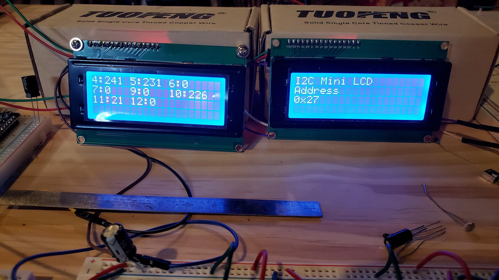
If I keep the solar panels deployed, they will get damaged underwater. No reason to keep them deployed, when the sun isn’t overhead and providing enough light. I found four Photoresistors and connected one up to each of the slaves. The current readings are sent to the master controller and displayed on LCD 0x24 and LCD 0x27. pr.py is the main Pi file. The Photo Resistors are on the Arduino devices. I use the I2C connection to the Raspberry Pi to display the output on I2C Mini LCD screens.

Arduino 4 Slave
// Wire Slave Receiver
// by Nicholas Zambetti <http://www.zambetti.com>

// Demonstrates use of the Wire library
// Receives data as an I2C/TWI slave device
// Refer to the "Wire Master Writer" example for use with this

// Created 29 March 2006

// This example code is in the public domain.

// 04-Feb-2018 mcarter adapted
#include <Wire.h>

const int ledPin = 13; // onboard LED
int ValueA3 = 0;
static_assert(LOW == 0, "Expecting LOW to be 0");

void requestEvent()
{
Wire.write(ValueA3);
}

void setup() {
  Serial.begin(9600);
  Wire.begin(0x4);                // join i2c bus with address #4

  Wire.onReceive(receiveEvent); // register event
  Wire.onRequest(requestEvent);  // send date to Pi

  pinMode(ledPin, OUTPUT);
  digitalWrite(ledPin, LOW); // turn it off
}

void loop() {
  delay(100);

  // Photo Resistor
  ValueA3 = analogRead(A3);
  ValueA3 = map(ValueA3, 0, 1023, 0, 255);

  Serial.print(ValueA3);
  Serial.print("\n");
  // Photo Resistor
}

// function that executes whenever data is received from master
// this function is registered as an event, see setup()
void receiveEvent(int howMany) {
  while (Wire.available()) { // loop through all but the last
    char c = Wire.read(); // receive byte as a character
    digitalWrite(ledPin, c);
  }


}
Arduino 5
// Wire Slave Receiver
// by Nicholas Zambetti <http://www.zambetti.com>

// Demonstrates use of the Wire library
// Receives data as an I2C/TWI slave device
// Refer to the "Wire Master Writer" example for use with this

// Created 29 March 2006

// This example code is in the public domain.

// 04-Feb-2018 mcarter adapted
#include <Wire.h>

const int ledPin = 13; // onboard LED
int ValueA3 = 0;
static_assert(LOW == 0, "Expecting LOW to be 0");

void requestEvent()
{
Wire.write(ValueA3);
}

void setup() {
  Serial.begin(9600);
  Wire.begin(0x5);                // join i2c bus with address #5

  Wire.onReceive(receiveEvent); // register event
  Wire.onRequest(requestEvent);  // send date to Pi

  pinMode(ledPin, OUTPUT);
  digitalWrite(ledPin, LOW); // turn it off
}

void loop() {
  delay(100);

  // Photo Resistor
  ValueA3 = analogRead(A3);
  ValueA3 = map(ValueA3, 0, 1023, 0, 255);

  Serial.print(ValueA3);
  Serial.print("\n");
  // Photo Resistor
}

// function that executes whenever data is received from master
// this function is registered as an event, see setup()
void receiveEvent(int howMany) {
  while (Wire.available()) { // loop through all but the last
    char c = Wire.read(); // receive byte as a character
    digitalWrite(ledPin, c);
  }


}
Arduino 6
// Wire Slave Receiver
// by Nicholas Zambetti <http://www.zambetti.com>

// Demonstrates use of the Wire library
// Receives data as an I2C/TWI slave device
// Refer to the "Wire Master Writer" example for use with this

// Created 29 March 2006

// This example code is in the public domain.

// 04-Feb-2018 mcarter adapted
#include <Wire.h>

const int ledPin = 13; // onboard LED
static_assert(LOW == 0, "Expecting LOW to be 0");

void setup() {
  Wire.begin(0x6);                // join i2c bus with address #6
  Wire.onReceive(receiveEvent); // register event
  pinMode(ledPin, OUTPUT);
  digitalWrite(ledPin, LOW); // turn it off
}

void loop() {
  delay(100);
}

// function that executes whenever data is received from master
// this function is registered as an event, see setup()
void receiveEvent(int howMany) {
  while (Wire.available()) { // loop through all but the last
    char c = Wire.read(); // receive byte as a character
    digitalWrite(ledPin, c);
  }
}
Arduino Mega 7
// Wire Slave Receiver
// by Nicholas Zambetti <http://www.zambetti.com>

// Demonstrates use of the Wire library
// Receives data as an I2C/TWI slave device
// Refer to the "Wire Master Writer" example for use with this

// Created 29 March 2006

// This example code is in the public domain.

// 04-Feb-2018 mcarter adapted
#include <Wire.h>

const int ledPin = 13; // onboard LED
static_assert(LOW == 0, "Expecting LOW to be 0");

void setup() {
  Wire.begin(0x7);                // join i2c bus with address #7
  Wire.onReceive(receiveEvent); // register event
  pinMode(ledPin, OUTPUT);
  digitalWrite(ledPin, LOW); // turn it off
}

void loop() {
  delay(100);
}

// function that executes whenever data is received from master
// this function is registered as an event, see setup()
void receiveEvent(int howMany) {
  while (Wire.available()) { // loop through all but the last
    char c = Wire.read(); // receive byte as a character
    digitalWrite(ledPin, c);
  }
}
Arduino 9
// Wire Slave Receiver
// by Nicholas Zambetti <http://www.zambetti.com>

// Demonstrates use of the Wire library
// Receives data as an I2C/TWI slave device
// Refer to the "Wire Master Writer" example for use with this

// Created 29 March 2006

// This example code is in the public domain.

// 04-Feb-2018 mcarter adapted
#include <Wire.h>

const int ledPin = 13; // onboard LED
static_assert(LOW == 0, "Expecting LOW to be 0");

void setup() {
  Wire.begin(0x9);                // join i2c bus with address #9
  Wire.onReceive(receiveEvent); // register event
  pinMode(ledPin, OUTPUT);
  digitalWrite(ledPin, LOW); // turn it off
}

void loop() {
  delay(100);
}

// function that executes whenever data is received from master
// this function is registered as an event, see setup()
void receiveEvent(int howMany) {
  while (Wire.available()) { // loop through all but the last
    char c = Wire.read(); // receive byte as a character
    digitalWrite(ledPin, c);
  }
}
Arduino 10
// Wire Slave Receiver
// by Nicholas Zambetti <http://www.zambetti.com>

// Demonstrates use of the Wire library
// Receives data as an I2C/TWI slave device
// Refer to the "Wire Master Writer" example for use with this

// Created 29 March 2006

// This example code is in the public domain.

// 04-Feb-2018 mcarter adapted
#include <Wire.h>

const int ledPin = 13; // onboard LED
int ValueA3 = 0;
static_assert(LOW == 0, "Expecting LOW to be 0");

void requestEvent()
{
Wire.write(ValueA3);
}

void setup() {
  Serial.begin(9600);
  Wire.begin(0xa);                // join i2c bus with address #10 or a

  Wire.onReceive(receiveEvent); // register event
  Wire.onRequest(requestEvent);  // send date to Pi

  pinMode(ledPin, OUTPUT);
  digitalWrite(ledPin, LOW); // turn it off
}

void loop() {
  delay(100);

  // Photo Resistor
  ValueA3 = analogRead(A3);
  ValueA3 = map(ValueA3, 0, 1023, 0, 255);

  Serial.print(ValueA3);
  Serial.print("\n");
  // Photo Resistor
}

// function that executes whenever data is received from master
// this function is registered as an event, see setup()
void receiveEvent(int howMany) {
  while (Wire.available()) { // loop through all but the last
    char c = Wire.read(); // receive byte as a character
    digitalWrite(ledPin, c);
  }


}
Arduino 11
// Wire Slave Receiver
// by Nicholas Zambetti <http://www.zambetti.com>

// Demonstrates use of the Wire library
// Receives data as an I2C/TWI slave device
// Refer to the "Wire Master Writer" example for use with this

// Created 29 March 2006

// This example code is in the public domain.

// 04-Feb-2018 mcarter adapted
#include <Wire.h>

const int ledPin = 13; // onboard LED
static_assert(LOW == 0, "Expecting LOW to be 0");

void setup() {
  Wire.begin(0xb);                // join i2c bus with address #11 or b
  Wire.onReceive(receiveEvent); // register event
  pinMode(ledPin, OUTPUT);
  digitalWrite(ledPin, LOW); // turn it off
}

void loop() {
  delay(100);
}

// function that executes whenever data is received from master
// this function is registered as an event, see setup()
void receiveEvent(int howMany) {
  while (Wire.available()) { // loop through all but the last
    char c = Wire.read(); // receive byte as a character
    digitalWrite(ledPin, c);
  }
}
Arduino 12
// Wire Slave Receiver
// by Nicholas Zambetti <http://www.zambetti.com>

// Demonstrates use of the Wire library
// Receives data as an I2C/TWI slave device
// Refer to the "Wire Master Writer" example for use with this

// Created 29 March 2006

// This example code is in the public domain.

// 04-Feb-2018 mcarter adapted
#include <Wire.h>

const int ledPin = 13; // onboard LED
static_assert(LOW == 0, "Expecting LOW to be 0");

void setup() {
  Wire.begin(0xc);                // join i2c bus with address #12 or c
  Wire.onReceive(receiveEvent); // register event
  pinMode(ledPin, OUTPUT);
  digitalWrite(ledPin, LOW); // turn it off
}

void loop() {
  delay(100);
}

// function that executes whenever data is received from master
// this function is registered as an event, see setup()
void receiveEvent(int howMany) {
  while (Wire.available()) { // loop through all but the last
    char c = Wire.read(); // receive byte as a character
    digitalWrite(ledPin, c);
  }
}
I2C_Dev.py
from smbus import SMBus
from RPi.GPIO import RPI_REVISION
from time import sleep
from re import findall, match
from subprocess import check_output
from os.path import exists

# old and new versions of the RPi have swapped the two i2c buses
# they can be identified by RPI_REVISION (or check sysfs)
BUS_NUMBER = 0 if RPI_REVISION == 1 else 1

# other commands
LCD_CLEARDISPLAY = 0x01
LCD_RETURNHOME = 0x02
LCD_ENTRYMODESET = 0x04
LCD_DISPLAYCONTROL = 0x08
LCD_CURSORSHIFT = 0x10
LCD_FUNCTIONSET = 0x20
LCD_SETCGRAMADDR = 0x40
LCD_SETDDRAMADDR = 0x80

# flags for display entry mode
LCD_ENTRYRIGHT = 0x00
LCD_ENTRYLEFT = 0x02
LCD_ENTRYSHIFTINCREMENT = 0x01
LCD_ENTRYSHIFTDECREMENT = 0x00

# flags for display on/off control
LCD_DISPLAYON = 0x04
LCD_DISPLAYOFF = 0x00
LCD_CURSORON = 0x02
LCD_CURSOROFF = 0x00
LCD_BLINKON = 0x01
LCD_BLINKOFF = 0x00

# flags for display/cursor shift
LCD_DISPLAYMOVE = 0x08
LCD_CURSORMOVE = 0x00
LCD_MOVERIGHT = 0x04
LCD_MOVELEFT = 0x00

# flags for function set
LCD_8BITMODE = 0x10
LCD_4BITMODE = 0x00
LCD_2LINE = 0x08
LCD_1LINE = 0x00
LCD_5x10DOTS = 0x04
LCD_5x8DOTS = 0x00

# flags for backlight control
LCD_BACKLIGHT = 0x08
LCD_NOBACKLIGHT = 0x00

En = 0b00000100  # Enable bit
Rw = 0b00000010  # Read/Write bit
Rs = 0b00000001  # Register select bit

class I2CDevice:
    def __init__(self, addr=None, addr_default=None, bus=BUS_NUMBER):
        if not addr:
            # try autodetect address, else use default if provided
            try:
                self.addr = int('0x{}'.format(
                    findall("[0-9a-z]{2}(?!:)", check_output(['/usr/sbin/i2cdetect', '-y', BUS_NUMBER]))[0]), base=16) \
                    if exists('/usr/sbin/i2cdetect') else addr_default
            except:
                self.addr = addr_default
        else:
            self.addr = addr
        self.bus = SMBus(bus)

    # write a single command
    def write_cmd(self, cmd):
        self.bus.write_byte(self.addr, cmd)
        sleep(0.0001)

    # write a command and argument
    def write_cmd_arg(self, cmd, data):
        self.bus.write_byte_data(self.addr, cmd, data)
        sleep(0.0001)

    # write a block of data
    def write_block_data(self, cmd, data):
        self.bus.write_block_data(self.addr, cmd, data)
        sleep(0.0001)

    # read a single byte
    def read(self):
        return self.bus.read_byte(self.addr)

    # read
    def read_data(self, cmd):
        return self.bus.read_byte_data(self.addr, cmd)

    # read a block of data
    def read_block_data(self, cmd):
        return self.bus.read_block_data(self.addr, cmd)


class Lcd:
    def __init__(self):
        self.lcd = I2CDevice(addr_default=0x27)
        self.lcd_write(0x03)
        self.lcd_write(0x03)
        self.lcd_write(0x03)
        self.lcd_write(0x02)
        self.lcd_write(LCD_FUNCTIONSET | LCD_2LINE | LCD_5x8DOTS | LCD_4BITMODE)
        self.lcd_write(LCD_DISPLAYCONTROL | LCD_DISPLAYON)
        self.lcd_write(LCD_CLEARDISPLAY)
        self.lcd_write(LCD_ENTRYMODESET | LCD_ENTRYLEFT)
        sleep(0.2)

    # clocks EN to latch command
    def lcd_strobe(self, data):
        self.lcd.write_cmd(data | En | LCD_BACKLIGHT)
        sleep(.0005)
        self.lcd.write_cmd(((data & ~En) | LCD_BACKLIGHT))
        sleep(.0001)

    def lcd_write_four_bits(self, data):
        self.lcd.write_cmd(data | LCD_BACKLIGHT)
        self.lcd_strobe(data)

    # write a command to lcd
    def lcd_write(self, cmd, mode=0):
        self.lcd_write_four_bits(mode | (cmd & 0xF0))
        self.lcd_write_four_bits(mode | ((cmd << 4) & 0xF0))

    # put string function
    def lcd_display_string(self, string, line):
        if line == 1:
            self.lcd_write(0x80)
        if line == 2:
            self.lcd_write(0xC0)
        if line == 3:
            self.lcd_write(0x94)
        if line == 4:
            self.lcd_write(0xD4)
        for char in string:
            self.lcd_write(ord(char), Rs)

    # put extended string function. Extended string may contain placeholder like {0xFF} for
    # displaying the particular symbol from the symbol table
    def lcd_display_extended_string(self, string, line):
        if line == 1:
            self.lcd_write(0x80)
        if line == 2:
            self.lcd_write(0xC0)
        if line == 3:
            self.lcd_write(0x94)
        if line == 4:
            self.lcd_write(0xD4)
        # Process the string
        while string:
            # Trying to find pattern {0xFF} representing a symbol
            result = match(r'\{0[xX][0-9a-fA-F]{2}\}', string)
            if result:
                self.lcd_write(int(result.group(0)[1:-1], 16), Rs)
                string = string[6:]
            else:
                self.lcd_write(ord(string[0]), Rs)
                string = string[1:]

    # clear lcd and set to home
    def lcd_clear(self):
        self.lcd_write(LCD_CLEARDISPLAY)
        self.lcd_write(LCD_RETURNHOME)

    # backlight control (on/off)
    # options: lcd_backlight(1) = ON, lcd_backlight(0) = OFF
    def lcd_backlight(self, state):
        if state == 1:
            self.lcd.write_cmd(LCD_BACKLIGHT)
        elif state == 0:
            self.lcd.write_cmd(LCD_NOBACKLIGHT)

class CustomCharacters:
    def __init__(self, lcd):
        self.lcd = lcd
        # Data for custom character #1. Code {0x00}.
        self.char_1_data = ["11111",
                            "10001",
                            "10001",
                            "10001",
                            "10001",
                            "10001",
                            "10001",
                            "11111"]
        # Data for custom character #2. Code {0x01}
        self.char_2_data = ["11111",
                            "10001",
                            "10001",
                            "10001",
                            "10001",
                            "10001",
                            "10001",
                            "11111"]
        # Data for custom character #3. Code {0x02}
        self.char_3_data = ["11111",
                            "10001",
                            "10001",
                            "10001",
                            "10001",
                            "10001",
                            "10001",
                            "11111"]
        # Data for custom character #4. Code {0x03}
        self.char_4_data = ["11111",
                            "10001",
                            "10001",
                            "10001",
                            "10001",
                            "10001",
                            "10001",
                            "11111"]
        # Data for custom character #5. Code {0x04}
        self.char_5_data = ["11111",
                            "10001",
                            "10001",
                            "10001",
                            "10001",
                            "10001",
                            "10001",
                            "11111"]
        # Data for custom character #6. Code {0x05}
        self.char_6_data = ["11111",
                            "10001",
                            "10001",
                            "10001",
                            "10001",
                            "10001",
                            "10001",
                            "11111"]
        # Data for custom character #7. Code {0x06}
        self.char_7_data = ["11111",
                            "10001",
                            "10001",
                            "10001",
                            "10001",
                            "10001",
                            "10001",
                            "11111"]
        # Data for custom character #8. Code {0x07}
        self.char_8_data = ["11111",
                            "10001",
                            "10001",
                            "10001",
                            "10001",
                            "10001",
                            "10001",
                            "11111"]

    # load custom character data to CG RAM for later use in extended string. Data for
    # characters is hold in file custom_characters.txt in the same folder as i2c_dev.py
    # file. These custom characters can be used in printing of extended string with a
    # placeholder with desired character codes: 1st - {0x00}, 2nd - {0x01}, 3rd - {0x02},
    # 4th - {0x03}, 5th - {0x04}, 6th - {0x05}, 7th - {0x06} and 8th - {0x07}.
    def load_custom_characters_data(self):
        self.chars_list = [self.char_1_data, self.char_2_data, self.char_3_data,
                           self.char_4_data, self.char_5_data, self.char_6_data,
                           self.char_7_data, self.char_8_data]

        # commands to load character adress to RAM srarting from desired base adresses:
        char_load_cmds = [0x40, 0x48, 0x50, 0x58, 0x60, 0x68, 0x70, 0x78]
        for char_num in range(8):
            # command to start loading data into CG RAM:
            self.lcd.lcd_write(char_load_cmds[char_num])
            for line_num in range(8):
                line = self.chars_list[char_num][line_num]
                binary_str_cmd = "0b000{0}".format(line)
                self.lcd.lcd_write(int(binary_str_cmd, 2), Rs)
pr.py
#! /usr/bin/env python3
#include <iostream>
#include <wiringPiI2C.h>
import time

from smbus import SMBus
import I2C_LCD_driver_24
import I2C_LCD_driver_27

lcd_24 = I2C_LCD_driver_24.lcd()
lcd_27 = I2C_LCD_driver_27.lcd()

ard_addr = bytearray([0x04, 0x05, 0x06, 0x07, 0x09, 0x0a, 0x0b, 0x0c])
number = bytearray([0, 0, 0, 0, 0, 0, 0, 0])

bus = SMBus(1) # indicates /dev/ic2-1
lcd_24 = I2C_LCD_driver_24.lcd()
lcd_27 = I2C_LCD_driver_27.lcd()
cnt = 0
while True:
    while cnt < 8:
        number[cnt] = bus.read_byte(ard_addr[cnt])
        print("Arduino", ard_addr[cnt], "PR reporting", number[cnt])
        bus.write_byte(ard_addr[cnt], 0x1) # switch it on
        time.sleep(2)
        bus.write_byte(ard_addr[cnt], 0x0) # switch it on
        cnt +=1
        ## LCD 24
        # Arduino 4
        str_addr = "{}".format(ard_addr[0])
        str_num = "{}".format(number[0])
        lcd_24.lcd_display_string(str_addr, 1, 0)
        lcd_24.lcd_display_string(": ", 1, 1)
        lcd_24.lcd_display_string(str_num, 1, 2)

        # Arduino 5
        str_addr = "{}".format(ard_addr[1])
        str_num = "{}".format(number[1])
        lcd_24.lcd_display_string(str_addr , 1, 6)
        lcd_24.lcd_display_string(": ", 1, 7)
        lcd_24.lcd_display_string(str_num, 1, 8)

        # Arduino 6
        str_addr = "{}".format(ard_addr[2])
        str_num = "{}".format(number[2])
        lcd_24.lcd_display_string(str_addr , 1, 12)
        lcd_24.lcd_display_string(": ", 1, 13)
        lcd_24.lcd_display_string(str_num, 1, 14)

        # Arduino 7
        str_addr = "{}".format(ard_addr[3])
        str_num = "{}".format(number[3])
        lcd_24.lcd_display_string(str_addr, 2, 0)
        lcd_24.lcd_display_string(": ", 2, 1)
        lcd_24.lcd_display_string(str_num, 2, 2)

        # Arduino 8
        str_addr = "{}".format(ard_addr[4])
        str_num = "{}".format(number[4])
        lcd_24.lcd_display_string(str_addr , 2, 6)
        lcd_24.lcd_display_string(": ", 2, 7)
        lcd_24.lcd_display_string(str_num, 2, 8)

        # Arduino 9
        str_addr = "{}".format(ard_addr[5])
        str_num = "{}".format(number[5])
        lcd_24.lcd_display_string(str_addr , 2, 12)
        lcd_24.lcd_display_string(": ", 2, 14)
        lcd_24.lcd_display_string(str_num, 2, 15)

        # Arduino 10
        str_addr = "{}".format(ard_addr[6])
        str_num = "{}".format(number[6])
        lcd_24.lcd_display_string(str_addr, 3, 0)
        lcd_24.lcd_display_string(": ", 3, 2)
        lcd_24.lcd_display_string(str_num, 3, 3)

        # Arduino 11
        str_addr = "{}".format(ard_addr[7])
        str_num = "{}".format(number[7])
        lcd_24.lcd_display_string(str_addr , 3, 6)
        lcd_24.lcd_display_string(": ", 3, 8)
        lcd_24.lcd_display_string(str_num, 3, 9)

        ##LCD 27
        lcd_27.lcd_display_string("I2C Mini LCD", 1, 0)
        lcd_27.lcd_display_string("Address", 2, 0)
        lcd_27.lcd_display_string("0x27", 3, 0)

    cnt = 0
    print(" ")
I2c_LCD_driver_24.py
# -*- coding: utf-8 -*-
# Original code found at:
# https://gist.github.com/DenisFromHR/cc863375a6e19dce359d

"""
Compiled, mashed and generally mutilated 2014-2015 by Denis Pleic
Made available under GNU GENERAL PUBLIC LICENSE

# Modified Python I2C library for Raspberry Pi
# as found on http://www.recantha.co.uk/blog/?p=4849
# Joined existing 'i2c_lib.py' and 'lcddriver.py' into a single library
# added bits and pieces from various sources
# By DenisFromHR (Denis Pleic)
# 2015-02-10, ver 0.1

"""

# i2c bus (0 -- original Pi, 1 -- Rev 2 Pi)
I2CBUS = 1

# LCD Address
ADDRESS = 0x24

import smbus
from time import sleep

class i2c_device:
   def __init__(self, addr, port=I2CBUS):
      self.addr = addr
      self.bus = smbus.SMBus(port)

# Write a single command
   def write_cmd(self, cmd):
      self.bus.write_byte(self.addr, cmd)
      sleep(0.0001)

# Write a command and argument
   def write_cmd_arg(self, cmd, data):
      self.bus.write_byte_data(self.addr, cmd, data)
      sleep(0.0001)

# Write a block of data
   def write_block_data(self, cmd, data):
      self.bus.write_block_data(self.addr, cmd, data)
      sleep(0.0001)

# Read a single byte
   def read(self):
      return self.bus.read_byte(self.addr)

# Read
   def read_data(self, cmd):
      return self.bus.read_byte_data(self.addr, cmd)

# Read a block of data
   def read_block_data(self, cmd):
      return self.bus.read_block_data(self.addr, cmd)


# commands
LCD_CLEARDISPLAY = 0x01
LCD_RETURNHOME = 0x02
LCD_ENTRYMODESET = 0x04
LCD_DISPLAYCONTROL = 0x08
LCD_CURSORSHIFT = 0x10
LCD_FUNCTIONSET = 0x20
LCD_SETCGRAMADDR = 0x40
LCD_SETDDRAMADDR = 0x80

# flags for display entry mode
LCD_ENTRYRIGHT = 0x00
LCD_ENTRYLEFT = 0x02
LCD_ENTRYSHIFTINCREMENT = 0x01
LCD_ENTRYSHIFTDECREMENT = 0x00

# flags for display on/off control
LCD_DISPLAYON = 0x04
LCD_DISPLAYOFF = 0x00
LCD_CURSORON = 0x02
LCD_CURSOROFF = 0x00
LCD_BLINKON = 0x01
LCD_BLINKOFF = 0x00

# flags for display/cursor shift
LCD_DISPLAYMOVE = 0x08
LCD_CURSORMOVE = 0x00
LCD_MOVERIGHT = 0x04
LCD_MOVELEFT = 0x00

# flags for function set
LCD_8BITMODE = 0x10
LCD_4BITMODE = 0x00
LCD_2LINE = 0x08
LCD_1LINE = 0x00
LCD_5x10DOTS = 0x04
LCD_5x8DOTS = 0x00

# flags for backlight control
LCD_BACKLIGHT = 0x08
LCD_NOBACKLIGHT = 0x00

En = 0b00000100 # Enable bit
Rw = 0b00000010 # Read/Write bit
Rs = 0b00000001 # Register select bit

class lcd:
   #initializes objects and lcd
   def __init__(self):
      self.lcd_device = i2c_device(ADDRESS)

      self.lcd_write(0x03)
      self.lcd_write(0x03)
      self.lcd_write(0x03)
      self.lcd_write(0x02)

      self.lcd_write(LCD_FUNCTIONSET | LCD_2LINE | LCD_5x8DOTS | LCD_4BITMODE)
      self.lcd_write(LCD_DISPLAYCONTROL | LCD_DISPLAYON)
      self.lcd_write(LCD_CLEARDISPLAY)
      self.lcd_write(LCD_ENTRYMODESET | LCD_ENTRYLEFT)
      sleep(0.2)


   # clocks EN to latch command
   def lcd_strobe(self, data):
      self.lcd_device.write_cmd(data | En | LCD_BACKLIGHT)
      sleep(.0005)
      self.lcd_device.write_cmd(((data & ~En) | LCD_BACKLIGHT))
      sleep(.0001)

   def lcd_write_four_bits(self, data):
      self.lcd_device.write_cmd(data | LCD_BACKLIGHT)
      self.lcd_strobe(data)

   # write a command to lcd
   def lcd_write(self, cmd, mode=0):
      self.lcd_write_four_bits(mode | (cmd & 0xF0))
      self.lcd_write_four_bits(mode | ((cmd << 4) & 0xF0))

   # write a character to lcd (or character rom) 0x09: backlight | RS=DR<
   # works!
   def lcd_write_char(self, charvalue, mode=1):
      self.lcd_write_four_bits(mode | (charvalue & 0xF0))
      self.lcd_write_four_bits(mode | ((charvalue << 4) & 0xF0))

   # put string function with optional char positioning
   def lcd_display_string(self, string, line=1, pos=0):
    if line == 1:
      pos_new = pos
    elif line == 2:
      pos_new = 0x40 + pos
    elif line == 3:
      pos_new = 0x14 + pos
    elif line == 4:
      pos_new = 0x54 + pos

    self.lcd_write(0x80 + pos_new)

    for char in string:
      self.lcd_write(ord(char), Rs)

   # clear lcd and set to home
   def lcd_clear(self):
      self.lcd_write(LCD_CLEARDISPLAY)
      self.lcd_write(LCD_RETURNHOME)

   # define backlight on/off (lcd.backlight(1); off= lcd.backlight(0)
   def backlight(self, state): # for state, 1 = on, 0 = off
      if state == 1:
         self.lcd_device.write_cmd(LCD_BACKLIGHT)
      elif state == 0:
         self.lcd_device.write_cmd(LCD_NOBACKLIGHT)

   # add custom characters (0 - 7)
   def lcd_load_custom_chars(self, fontdata):
      self.lcd_write(0x40);
      for char in fontdata:
         for line in char:
            self.lcd_write_char(line)
I2c_LCD_driver_27.py
# -*- coding: utf-8 -*-
# Original code found at:
# https://gist.github.com/DenisFromHR/cc863375a6e19dce359d

"""
Compiled, mashed and generally mutilated 2014-2015 by Denis Pleic
Made available under GNU GENERAL PUBLIC LICENSE

# Modified Python I2C library for Raspberry Pi
# as found on http://www.recantha.co.uk/blog/?p=4849
# Joined existing 'i2c_lib.py' and 'lcddriver.py' into a single library
# added bits and pieces from various sources
# By DenisFromHR (Denis Pleic)
# 2015-02-10, ver 0.1

"""

# i2c bus (0 -- original Pi, 1 -- Rev 2 Pi)
I2CBUS = 1

# LCD Address
ADDRESS = 0x27

import smbus
from time import sleep

class i2c_device:
   def __init__(self, addr, port=I2CBUS):
      self.addr = addr
      self.bus = smbus.SMBus(port)

# Write a single command
   def write_cmd(self, cmd):
      self.bus.write_byte(self.addr, cmd)
      sleep(0.0001)

# Write a command and argument
   def write_cmd_arg(self, cmd, data):
      self.bus.write_byte_data(self.addr, cmd, data)
      sleep(0.0001)

# Write a block of data
   def write_block_data(self, cmd, data):
      self.bus.write_block_data(self.addr, cmd, data)
      sleep(0.0001)

# Read a single byte
   def read(self):
      return self.bus.read_byte(self.addr)

# Read
   def read_data(self, cmd):
      return self.bus.read_byte_data(self.addr, cmd)

# Read a block of data
   def read_block_data(self, cmd):
      return self.bus.read_block_data(self.addr, cmd)


# commands
LCD_CLEARDISPLAY = 0x01
LCD_RETURNHOME = 0x02
LCD_ENTRYMODESET = 0x04
LCD_DISPLAYCONTROL = 0x08
LCD_CURSORSHIFT = 0x10
LCD_FUNCTIONSET = 0x20
LCD_SETCGRAMADDR = 0x40
LCD_SETDDRAMADDR = 0x80

# flags for display entry mode
LCD_ENTRYRIGHT = 0x00
LCD_ENTRYLEFT = 0x02
LCD_ENTRYSHIFTINCREMENT = 0x01
LCD_ENTRYSHIFTDECREMENT = 0x00

# flags for display on/off control
LCD_DISPLAYON = 0x04
LCD_DISPLAYOFF = 0x00
LCD_CURSORON = 0x02
LCD_CURSOROFF = 0x00
LCD_BLINKON = 0x01
LCD_BLINKOFF = 0x00

# flags for display/cursor shift
LCD_DISPLAYMOVE = 0x08
LCD_CURSORMOVE = 0x00
LCD_MOVERIGHT = 0x04
LCD_MOVELEFT = 0x00

# flags for function set
LCD_8BITMODE = 0x10
LCD_4BITMODE = 0x00
LCD_2LINE = 0x08
LCD_1LINE = 0x00
LCD_5x10DOTS = 0x04
LCD_5x8DOTS = 0x00

# flags for backlight control
LCD_BACKLIGHT = 0x08
LCD_NOBACKLIGHT = 0x00

En = 0b00000100 # Enable bit
Rw = 0b00000010 # Read/Write bit
Rs = 0b00000001 # Register select bit

class lcd:
   #initializes objects and lcd
   def __init__(self):
      self.lcd_device = i2c_device(ADDRESS)

      self.lcd_write(0x03)
      self.lcd_write(0x03)
      self.lcd_write(0x03)
      self.lcd_write(0x02)

      self.lcd_write(LCD_FUNCTIONSET | LCD_2LINE | LCD_5x8DOTS | LCD_4BITMODE)
      self.lcd_write(LCD_DISPLAYCONTROL | LCD_DISPLAYON)
      self.lcd_write(LCD_CLEARDISPLAY)
      self.lcd_write(LCD_ENTRYMODESET | LCD_ENTRYLEFT)
      sleep(0.2)


   # clocks EN to latch command
   def lcd_strobe(self, data):
      self.lcd_device.write_cmd(data | En | LCD_BACKLIGHT)
      sleep(.0005)
      self.lcd_device.write_cmd(((data & ~En) | LCD_BACKLIGHT))
      sleep(.0001)

   def lcd_write_four_bits(self, data):
      self.lcd_device.write_cmd(data | LCD_BACKLIGHT)
      self.lcd_strobe(data)

   # write a command to lcd
   def lcd_write(self, cmd, mode=0):
      self.lcd_write_four_bits(mode | (cmd & 0xF0))
      self.lcd_write_four_bits(mode | ((cmd << 4) & 0xF0))

   # write a character to lcd (or character rom) 0x09: backlight | RS=DR<
   # works!
   def lcd_write_char(self, charvalue, mode=1):
      self.lcd_write_four_bits(mode | (charvalue & 0xF0))
      self.lcd_write_four_bits(mode | ((charvalue << 4) & 0xF0))

   # put string function with optional char positioning
   def lcd_display_string(self, string, line=1, pos=0):
    if line == 1:
      pos_new = pos
    elif line == 2:
      pos_new = 0x40 + pos
    elif line == 3:
      pos_new = 0x14 + pos
    elif line == 4:
      pos_new = 0x54 + pos

    self.lcd_write(0x80 + pos_new)

    for char in string:
      self.lcd_write(ord(char), Rs)

   # clear lcd and set to home
   def lcd_clear(self):
      self.lcd_write(LCD_CLEARDISPLAY)
      self.lcd_write(LCD_RETURNHOME)

   # define backlight on/off (lcd.backlight(1); off= lcd.backlight(0)
   def backlight(self, state): # for state, 1 = on, 0 = off
      if state == 1:
         self.lcd_device.write_cmd(LCD_BACKLIGHT)
      elif state == 0:
         self.lcd_device.write_cmd(LCD_NOBACKLIGHT)

   # add custom characters (0 - 7)
   def lcd_load_custom_chars(self, fontdata):
      self.lcd_write(0x40);
      for char in fontdata:
         for line in char:
            self.lcd_write_char(line)